


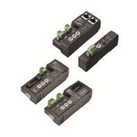
Sensor Communications Unit
E3NW
 The Next-generation Sensor Networking Units That Revolutionize the Workplace from Introduction and Startup though Operation
Sensor Communications Unit
EtherCAT
|
Model |
E3NW-ECT |
|
Connectable Sensor Amplifier Units |
N-Smart |
|
Power supply voltage |
24 VDC (20.4 to 26.4 V) |
|
Power and current consumption |
2.4 W max. (Not including the power supplied to Sensors.), |
|
Indicators |
L/A IN indicator (green), L/A OUT indicator (green), PWR indicator (green), |
|
Vibration resistance (destruction) |
10 to 60 Hz with a 0.7-mm double amplitude, 50 m/s2 at 60 to 150 Hz, for 1.5 |
|
Shock resistance (destruction) |
150 m/s2 for 3 times each in X, Y, and Z directions |
|
Ambient temperature range |
Operating: 0 to 55°C; *3 |
|
Ambient humidity range |
Operating and storage: 25% to 85% (with no condensation) |
|
Maximum connectable Sensors *3 *4 |
30 (when connected to an OMRON NJ-series Controller, 16 for E2NC-EA10/ |
|
Maximum connectable Distributed |
8 |
|
Insulation resistance |
20 MΩ min. (at 500 VDC) |
|
Dielectric strength |
500 VAC at 50/60 Hz for 1 min |
|
Mounting method |
35-mm DIN track - mounting |
|
Weight (packed state/Unit only) |
Approx. 185 g/approx. 95 g |
|
Materials |
Polycarbonate |
|
Accessories |
Power supply connector, communications connector for E3NW-DS connection, |
1. The E3NX-CA0 is supported for firmware version 1.06 or higher (Sensor Communications Units manufactured in
June 2016 or later).
2. The E9NC-TA0 is supported for firmware version 1.03 or higher (Sensor Communications Units manufactured in
July 2014 or later).
3. Temperature Limitations Based on Number of Connected Amplifier Units:
Groups of 1 or 2 Amplifier Units: 0 to 55°C, Groups of 3 to 10 Amplifier Units: 0 to 50°C, Groups of 11 to 16 Amplifier
Units: 0 to 45°C, Groups of 17 to 30 Amplifier Units: 0 to 40°C
4. This is the total number of Sensors that can be connected to the Sensor Communications Unit and Distributed Sensor
Units.
Communications Specifications
|
Item |
Specification |
|
Communications protocol |
Dedicated protocol for EtherCAT |
|
Modulation |
Baseband method |
|
Baud rate |
100 Mbps |
|
Physical layer |
100BASE-TX (IEEE 802.3u) |
|
Topology |
Daisy chain |
|
Communications media |
STP category 5 or higher |
|
Communications distance |
Distance between nodes: 100 m max. |
|
Noise immunity |
Conforms to IEC 61000-4-4, 1 kV or higher |
|
Node address setting method |
Set with decimal rotary switches or software *1 |
|
Node address range |
000 to 192 *2 |
1. The software setting is used when the node address setting switches are set to 0.
2. The range depends on the EtherCAT master that is used. Refer to the E3NW-ECT EtherCAT Digital Sensor
Communications Unit Operation Manual (Cat. No. E429) for details.
CompoNet
|
Model |
E3NW-CRT |
|
Connectable Sensor Amplifier Units |
N-Smart |
|
Power supply voltage |
14 to 26.4 VDC |
|
Power and current consumption |
At 24 VDC |
|
Indicators |
MS (Machine Status) indicator (green/red), NS (Network Status) indicator |
|
Vibration resistance (destruction) |
10 to 60 Hz with a 0.7-mm double amplitude, 50 m/s2 at 60 to 150 Hz, for 1.5 |
|
Shock resistance (destruction) |
150 m/s2 for 3 times each in X, Y, and Z directions |
|
Ambient temperature range |
Operating: 0 to 55°C; *1 |
|
Ambient humidity range |
Operating and storage: 25% to 85% (with no condensation) |
|
Maximum connectable Sensors *1 |
16 *2 |
|
Maximum connectable Distributed |
8 |
|
Insulation resistance |
20 MΩ min. (at 500 VDC) |
|
Dielectric strength |
500 VAC at 50/60 Hz for 1 min |
|
Mounting method |
35-mm DIN track - mounting |
|
Weight (packed state/Unit only) |
Approx. 165 g/approx. 70 g |
|
Materials |
Polycarbonate |
|
Accessories |
Communications connector for E3NW-DS connection, DIN Track End Plates |
1. Temperature Limitations Based on Number of Connected Amplifier Units:
Groups of 1 or 2 Amplifier Units: 0 to 55°C, Groups of 3 to 10 Amplifier Units: 0 to 50°C, Groups of 11 to 16 Amplifier
Units: 0 to 45°C
2. This is the total number of Sensors that can be connected to the Sensor Communications Unit and Distributed Sensor
Units.
Communications Specifications
|
Item |
Specifications |
|
Communications method |
Dedicated protocol for CompoNet |
|
Types of communications |
Remote I/O communications (program-free, constant sharing of data) and message |
|
Baud rate |
4 Mbps, 3 Mbps, 1.5 Mbps, 93.75 kbps |
|
Modulation |
Baseband method |
|
Coding |
Manchester code |
|
Error control |
Manchester encoding rules and CRC |
|
Communications media |
The following media can be used. |
|
Communications |
Refer to 1-2-1 Cable Types, Maximum Distances, and Number of Slave Units in the |
|
Signal lines |
Two lines: BDH (communications data high) and BDL (communications data low) |
|
Power lines |
Two lines: BS+ and BS- (power for communications and internal Slave Unit circuits) |
|
Connection forms |
Round Cable II, Flat Cable I, or Flat Cable II at a baud rate of 93.75 kbps: No restrictions |
|
Connections for Slave Units and Repeater Units: T-branch or multidrop connections |
|
|
Noise immunity |
Conforms to IEC 61000-4-4, 1 kV or higher |
|
Address setting method |
Decimal rotary address switch |
|
Address range |
0 to 62 |
CC-Link
|
Model |
E3NW-CCL |
|
Connectable Sensor Amplifier Units |
N-Smart |
|
Power supply voltage |
24 VDC (20.4 to 26.4 V) |
|
Power and current consumption |
2.4 W max. (Not including the power supplied to Sensors.), |
|
Indicators |
RUN indicator (green), ERROR indicator (red), and SS (Sensor Status) indicator |
|
Vibration resistance (destruction) |
10 to 60 Hz with a 0.7-mm double amplitude, 50 m/s2 at 60 to 150 Hz, for 1.5 |
|
Shock resistance (destruction) |
150 m/s2 for 3 times each in X, Y, and Z directions |
|
Ambient temperature range |
Operating: 0 to 55°C; *2 |
|
Ambient humidity range |
Operating and storage: 25% to 85% (with no condensation) |
|
Maximum connectable Sensors *2 |
16 *3 |
|
Maximum connectable Distributed |
8 |
|
Insulation resistance |
20 MΩ min. (at 500 VDC) |
|
Dielectric strength |
500 VAC at 50/60 Hz for 1 min |
|
Mounting method |
35-mm DIN track - mounting |
|
Weight (packed state/Unit only) |
Approx. 180 g/approx. 80 g |
|
Materials |
Polycarbonate |
|
Accessories |
Power Supply Connector, E3NW-DS Communications Connector, |
1. The E9NC-TA0 is supported for firmware version 1.03 or higher (Sensor Communications Units manufactured in
July 2014 or later).
2. Temperature Limitations Based on Number of Connected Amplifier Units:
Groups of 1 or 2 Amplifier Units: 0 to 55°C, Groups of 3 to 10 Amplifier Units: 0 to 50°C, Groups of 11 to 16 Amplifier
Units: 0 to 45°C
3. This is the total number of Sensors that can be connected to the Sensor Communications Unit and Distributed Sensor
Units.
Communications Specifications
|
Item |
Specifications |
|
Communications protocol |
Dedicated protocol for CC-Link |
|
Communications method |
Broadcast polling |
|
Baud rate |
10 Mbps/5 Mbps/2.5 Mbps/625 kbps/156 kbps |
|
Physical layer |
Bus (based on EIA RS485) |
|
Topology |
Daisy chain (T-branching can be used.) |
|
Communications media |
CC-Link Cables |
|
Communications distance |
Cable length between nodes: 20 cm min. |
|
Noise immunity |
Conforms to IEC 61000-4-4, 1 kV or higher |
|
Address setting method |
Decimal rotary address switch |
|
Address range |
64 max. * |
|
Synchronization mode |
Cyclic transmissions (synchronization) |
* The range depends on the CC-Link master that is used. Refer to 5-3-2 Node Setting Switches in the E3NW-CCL CC-
Link Digital Sensor Communications Unit Operation Manual (Cat. No. E431) for details.
Distributed Sensor Unit
|
Model |
E3NW-DS |
|
Connectable Sensor Amplifier Units |
N-Smart |
|
Power supply voltage |
24 VDC (20.4 to 26.4 V) |
|
Power and current consumption |
2 W max. (Not including the power supplied to Sensors.), |
|
Indicators |
RUN indicator (green) and SS (Sensor Status) indicator (green/red) |
|
Vibration resistance (destruction) |
10 to 60 Hz with a 0.7-mm double amplitude, 50 m/s2 at 60 to 150 Hz, for 1.5 |
|
Shock resistance (destruction) |
150 m/s2 for 3 times each in X, Y, and Z directions |
|
Ambient temperature range |
Operating: 0 to 55°C; * |
|
Ambient humidity range |
Operating and storage: 25% to 85% (with no condensation) |
|
Maximum connectable Sensors * |
10 |
|
Insulation resistance |
20 MΩ min. (at 500 VDC) |
|
Dielectric strength |
500 VAC at 50/60 Hz for 1 min |
|
Mounting method |
35-mm DIN track - mounting |
|
Weight (packed state/Unit only) |
Approx. 160 g/approx. 40 g |
|
Materials |
Polycarbonate |
|
Accessories |
Power supply/communications connector, DIN Track End Plates (2 pieces), |
* Temperature Limitations Based on Number of Connected Amplifier Units:
Groups of 1 or 2 Amplifier Units: 0 to 55°C, Groups of 3 to 10 Amplifier Units: 0 to 50°C