


Simple Fiber Amplifier Unit
E3X-SD / NA
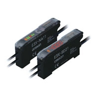 Simple and Affordable Fiber Amplifier Units
Fiber Amplifier Units
|
Type |
Digital display and direct key |
Bar display and adjuster setting |
|||
|
Standard models |
Standard |
High-speed |
Water-resistant |
||
|
Model |
E3X-SD[] |
E3X-NA[] |
E3X-NA[]F |
E3X-NA[]V |
|
|
Light source |
Red, 4-element LED (625 nm) |
Red, |
Red, |
Red LED (680 nm) |
|
|
Power supply voltage |
12 to 24 VDC ±10%, ripple (p-p): 10% max. |
||||
|
Power consumption/ |
At Power Supply Voltage of 24 VDC |
At Power Supply Voltage of 24 VDC |
|||
|
Control output |
Open-collector output (NPN or PNP) |
Open-collector output (NPN or PNP) |
|||
|
Response time |
Operate or reset: 200 μs max. *1 |
Operate: |
Operate or reset: |
||
|
Sensitivity adjustment |
UP/DOWN direct key setting, |
8-turn sensitivity adjuster (with indicator) |
|||
|
Protection circuits |
Power supply reverse polarity |
Power supply reverse polarity protection, |
|||
|
Timer function |
--- |
No timer, OFF-delay timer; or Timer selector |
|||
|
Mutual interference |
Up to 5 Amplifiers (optically synchronized) *2 |
None |
Up to 5 Amplifiers |
||
|
Ambient illumination |
Receiver side |
||||
|
Number of gang- |
16 max. (The ambient temperature specification depends on the number of gang-mounted |
||||
|
Ambient temperature |
Operating: Groups of 1 to 3 Amplifiers: - 25 °C to 55 °C |
||||
|
Ambient humidity range |
Operating and storage: 35% to 85% |
Operating: 35% to 85% |
|||
|
Insulation resistance |
20 MΩ. min. (at 500 VDC) |
||||
|
Dielectric strength |
1,000 VAC at 50/60 Hz for 1 minute *3 |
||||
|
Vibration resistance |
Destruction: 10 to 55 Hz with a 1.5-mm double amplitude for 2 hours each in X, Y and Z |
||||
|
Shock resistance |
Destruction: 500 m/s2, for 3 times each in X, Y and Z directions |
||||
|
Degree of protection |
IEC 60529 IP50 (with Protective Cover attached) |
IEC 60529 IP66 |
|||
|
Connection method |
Pre-wired (standard cable length: 2 m), or connector |
||||
|
Weight (packed state) *4 |
Pre-wired model: Approx. 100 g, Model with connector: Approx. 55 g |
||||
|
Material |
Case |
Polybutylene terephthalate (PBT) |
|||
|
Cover |
Polycarbonate (PC) |
Polyethersulfone |
|||
|
Accessories |
Instruction manual |
||||
Amplifier Unit Connectors (Wire-saving Connectors)
|
Model |
E3X-CN11 |
E3X-CN12 |
|
|
Rated current |
2.5 A |
||
|
Rated voltage |
50 V |
||
|
Contact resistance |
20 mΩ max. (20 mVDC max., 100 mA max.) |
||
|
Number of insertions |
Destruction: 50 times (for connection to the Fiber Amplifier Unit and the adjacent Connector) |
||
|
Material |
Housing |
Polybutylene terephthalate (PBT) |
|
|
Contact |
Phosphor bronze/gold-plated nickel |
||
|
Weight (packed state) |
Approx. 55 g |
Approx. 25 g |
|
Sensing distance
Threaded Models
|
Detection method |
Sensing direction |
Size |
Model |
Sensing distance (mm) |
||
|
E3X-SD[] |
E3X-NA[]F |
E3X-NA[]V |
||||
|
Through-beam |
Right-angle |
M4 |
E32-T11N 2M |
530 |
160 |
280 |
|
E32-LT11N 2M |
1,800 |
600 |
900 |
|||
|
Straight |
E32-T11R 2M |
560 |
160 |
280 |
||
|
E32-LT11 2M |
2,100 |
700 |
1,050 |
|||
|
E32-LT11R 2M |
1,800 |
600 |
900 |
|||
|
Reflective |
Right-angle |
M3 |
E32-C31N 2M |
25 |
7.5 |
13 |
|
E32-C21N 2M |
65 |
21 |
32 |
|||
|
M4 |
E32-D21N 2M |
170 |
56 |
85 |
||
|
M6 |
E32-C11N 2M |
170 |
50 |
85 |
||
|
E32-LD11N 2M |
170 |
56 |
85 |
|||
|
Straight |
M3 |
E32-D21R 2M |
30 |
10 |
15 |
|
|
E32-C31 2M |
80 |
26 |
40 |
|||
|
E32-C31M 1M |
||||||
|
M4 |
E32-D211R 2M |
30 |
10 |
15 |
||
|
M6 |
E32-D11R 2M |
180 |
60 |
90 |
||
|
E32-CC200 2M |
300 |
100 |
150 |
|||
|
E32-LD11 2M |
180 |
60 |
90 |
|||
|
E32-LD11R 2M |
170 |
56 |
85 |
|||
Cylindrical Models
|
Detection method |
Size |
Sensing direction |
Model |
Sensing distance (mm) |
||
|
E3X-SD[] |
E3X-NA[]F |
E3X-NA[]V |
||||
|
Through-beam |
1 dia. |
Top-view |
E32-T223R 2M |
120 |
36 |
60 |
|
1.5 dia. |
E32-T22B 2M |
200 |
60 |
100 |
||
|
3 dia. |
E32-T12R 2M |
560 |
160 |
280 |
||
|
Side-view |
E32-T14LR 2M |
220 |
66 |
110 |
||
|
Reflective |
1.5 dia. |
Top-view |
E32-D22B 2M |
30 |
10 |
15 |
|
1.5 dia. + 0.5 dia. |
E32-D43M 1M |
6 |
2 |
3 |
||
|
3 dia. |
E32-D22R 2M |
30 |
10 |
15 |
||
|
E32-D221B 2M |
70 |
20 |
35 |
|||
|
E32-D32L 2M |
160 |
50 |
80 |
|||
|
3 dia. + 0.8 dia. |
E32-D33 2M |
16 |
4 |
10 |
||
Flat Models
|
Detection method |
Sensing direction |
Model |
Sensing distance (mm) |
||
|
E3X-SD[] |
E3X-NA[]F |
E3X-NA[]V |
|||
|
Through-beam |
Top-view |
E32-T15XR 2M |
560 |
160 |
280 |
|
Side-view |
E32-T15YR 2M |
220 |
66 |
110 |
|
|
Flat-view |
E32-T15ZR 2M |
||||
|
Reflective |
Top-view |
E32-D15XR 2M |
180 |
60 |
90 |
|
Side-view |
E32-D15YR 2M |
40 |
10 |
20 |
|
|
Flat-view |
E32-D15ZR 2M |
||||
Sleeve Models
|
Detection method |
Sensing direction |
Model |
Sensing distance (mm) |
||
|
E3X-SD[] |
E3X-NA[]F |
E3X-NA[]V |
|||
|
Through-beam |
Side-view |
E32-T24R 2M |
60 |
18 |
30 |
|
E32-T24E 2M |
180 |
36 |
60 |
||
|
Top-view |
E32-T21-S1 2M |
130 |
43 |
65 |
|
|
E32-T33 1M |
40 |
13.5 |
20 |
||
|
E32-TC200BR 2M |
560 |
160 |
280 |
||
|
Reflective |
Side-view |
E32-D24R 2M |
14 |
4.6 |
7 |
|
E32-D24-S2 2M |
26 |
8 |
13 |
||
|
Top-view |
E32-D43M 1M |
6 |
2 |
3 |
|
|
E32-D331 2M |
3 |
1 |
1.5 |
||
|
E32-D33 2M |
16 |
4 |
10 |
||
|
E32-D32-S1 0.5M |
14 |
4 |
7 |
||
|
E32-D31-S1 0.5M |
|||||
|
E32-DC200F4R 2M |
30 |
10 |
15 |
||
|
E32-D22-S1 2M |
57 |
19 |
28 |
||
|
E32-D21-S3 2M |
|||||
|
E32-DC200BR 2M |
180 |
60 |
90 |
||
|
E32-D25-S3 2M |
57 |
19 |
28 |
||
Small-spot, Reflective
|
Type |
Spot |
Center distance |
Model |
Sensing distance (mm) |
||
|
E3X-SD[] |
E3X-NA[]F |
E3X-NA[]V |
||||
|
Variable |
0.1 to |
6 to 15 |
E32-C42 1M + E39-F3A |
Spot diameter of 0.1 to 0.6 mm at 6 to 15 mm. |
||
|
0.3 to |
10 to 30 |
E32-C42 1M + E39-F17 |
Spot diameter of 0.3 to 1.6 mm at 10 to 30 mm. |
|||
|
Parallel |
4 dia. |
0 to 20 |
E32-C31 2M + E39-F3C |
Spot diameter of 4 mm max. at 0 to 20 mm. |
||
|
E32-C31N 2M + E39-F3C |
||||||
|
Integrated |
0.1 dia. |
5 |
E32-C42S 1M |
Spot diameter of 0.1 mm at 5 mm. |
||
|
6 dia. |
50 |
E32-L15 2M |
Spot diameter of 6 mm at 50 mm. |
|||
|
Small- |
0.1 dia. |
7 |
E32-C41 1M + E39-F3A-5 |
Spot diameter of 0.1 mm at 7 mm. |
||
|
0.5 dia. |
E32-C31 2M + E39-F3A-5 |
Spot diameter of 0.5 mm at 5 mm. |
||||
|
E32-C31N 2M + E39-F3A-5 |
||||||
|
0.2 dia. |
17 |
E32-C41 1M + E39-F3B |
Spot diameter of 0.2 mm at 17 mm. |
|||
|
0.5 dia. |
E32-C31 2M + E39-F3B |
Spot diameter of 0.5 mm at 17 mm. |
||||
|
E32-C31N 2M + E39-F3B |
||||||
|
3 dia. |
50 |
E32-CC200 2M + E39-F18 |
Spot diameter of 3 mm at 50 mm. |
|||
|
E32-C11N 2M + E39-F18 |
||||||
High-power Beam
|
Type |
Sensing |
Aperture |
Model |
Sensing distance (mm) |
||
|
E3X-SD[] |
E3X-NA[]F |
E3X-NA[]V |
||||
|
Through-beam |
Right-angle |
15° |
E32-LT11N 2M |
1,800 |
600 |
900 |
|
Top-view |
10° |
E32-T17L 10M |
20,000 *1 |
8,400 |
14,000 |
|
|
15° |
E32-LT11 2M |
2,100 |
700 |
1,050 |
||
|
15° |
E32-LT11R 2M |
1,800 |
600 |
900 |
||
|
Side-view |
30° |
E32-T14 2M |
3,600 |
1,080 |
1,800 |
|
|
Through-beam |
Right-angle |
12° |
E32-T11N 2M + E39-F1 |
3,700 |
1,110 |
2,100 |
|
6° |
E32-T11N 2M + E39-F16 |
4,000 *2 |
2,000 |
3,600 |
||
|
Top-view |
12° |
E32-T11R 2M + E39-F1 |
4,000 *2 |
1,260 |
2,100 |
|
|
6° |
E32-T11R 2M + E39-F16 |
4,000 *2 |
2,000 |
3,600 |
||
|
Side-view |
60° |
E32-T11R 2M + E39-F2 |
440 |
130 |
220 |
|
|
Top-view |
12° |
E32-T11 2M + E39-F1 |
4,000 *2 |
1,200 |
2,000 |
|
|
6° |
E32-T11 2M + E39-F16 |
4,000 *2 |
2,600 |
4,000 *2 |
||
|
Side-view |
60° |
E32-T11 2M + E39-F2 |
720 |
200 |
360 |
|
|
Top-view |
12° |
E32-T51R 2M + E39-F1 |
2,000 |
720 |
1,650 |
|
|
6° |
E32-T51R 2M + E39-F16 |
4,000 *2 |
1,560 |
2,900 |
||
|
Side-view |
60° |
E32-T51R 2M + E39-F2 |
360 |
120 |
200 |
|
|
Top-view |
12° |
E32-T81R-S 2M + E39-F1 |
1,800 |
630 |
1,100 |
|
|
6° |
E32-T81R-S 2M + E39-F16 |
4,000 *2 |
1,300 |
2,300 |
||
|
Side-view |
60° |
E32-T81R-S 2M + E39-F2 |
280 |
84 |
140 |
|
|
Top-view |
12° |
E32-T61-S 2M + E39-F1 |
4,000 *2 |
1,800 |
3,000 |
|
|
6° |
E32-T61-S 2M + E39-F16 |
4,000 *2 |
2,340 |
3,900 |
||
|
Side-view |
60° |
E32-T61-S 2M + E39-F2 |
780 |
260 |
390 |
|
|
Top-view |
12° |
E32-T51 2M + E39-F1-33 |
2,400 |
720 |
1,400 |
|
|
6° |
E32-T51 2M + E39-F16 |
4,000 *2 |
3,120 |
4,000 *2 |
||
|
Reflective |
Top-view |
4° |
E32-D16 2M |
800 |
140 |
40 to 400 |
Narrow View
|
Detection method |
Sensing |
Aperture angle |
Model |
Sensing distance (mm) |
||
|
E3X-SD[] |
E3X-NA[]F |
E3X-NA[]V |
||||
|
Through-beam |
Side-view |
1.5° |
E32-A03 2M |
890 |
267 |
445 |
|
E32-A03-1 2M |
||||||
|
3.4° |
E32-A04 2M |
340 |
102 |
170 |
||
|
4° |
E32-T24SR 2M |
1170 |
360 |
600 |
||
|
E32-T24S 2M |
1400 |
420 |
700 |
|||
|
E32-T22S 2M |
2000 |
600 |
1000 |
|||
Detection without Background Interference
|
Detection |
Sensing |
Model |
Sensing distance (mm) |
||
|
E3X-SD[] |
E3X-NA[]F |
E3X-NA[]V |
|||
|
Limited- |
Flat-view |
E32-L16-N 2M |
0 to 15 |
0 to 12 |
0 to 15 |
|
E32-L24S 2M |
0 to 4 |
||||
|
Side-view |
E32-L25L 2M |
5.4 to 9 (center 7.2) |
5.4 to 8 (center 7.2) |
5.4 to 9 (center 7.2) |
|
Transparent Object Detection (Retro-reflective)
|
Detection |
Feature |
Size |
Model |
Sensing distance (mm) |
||
|
E3X-SD[] |
E3X-NA[]F |
E3X-NA[]V |
||||
|
Retroreflective |
Film detection |
M3 |
E32-C31 2M + |
220 |
50 |
75 |
|
Square |
- |
E32-R16 2M |
1,500 |
1,000 |
150 to 1,500 |
|
|
Threaded Models |
M6 |
E32-R21 2M |
10 to 250 |
250 |
10 to 250 |
|
|
Hex-shaped |
E32-LR11NP 2M + |
600 |
200 |
300 |
||
Transparent Object Detection (Limited-reflective)
|
Detection |
Feature |
Sensing |
Model |
Sensing distance (mm) |
||
|
E3X-SD[] |
E3X-NA[]F |
E3X-NA[]V |
||||
|
Retro- |
Small size |
Flat-view |
E32- L24S 2M |
0 to 4 |
||
|
Standard |
E32-L16-N 2M |
0 to 15 |
0 to 12 |
0 to 15 |
||
|
Glass substrate |
E32-A08 2M |
10 to 20 |
||||
|
Standard/ |
E32-A12 2M |
12 to 30 |
- |
- |
||
|
Side view form |
Side-view |
E32-L25L 2M |
5.4 to 9 |
5.4 to 8 |
5.4 to 9 |
|
|
Glass substrate |
Top-view |
E32-A09 2M |
15 to 38 (center 25) |
|||
Chemical-resistant, Oil-resistant
|
Detection |
Type |
Sensing |
Model |
Sensing distance (mm) |
||
|
E3X-SD[] |
E3X-NA[]F |
E3X-NA[]V |
||||
|
Through- |
Oil-resistant |
Right-angle |
E32-T11NF 2M |
4,000 * |
1,400 |
2,400 |
|
Chemical/ |
Top-view |
E32-T12F 2M |
3,200 |
960 |
1,600 |
|
|
E32-T11F 2M |
2,100 |
760 |
1,050 |
|||
|
Side-view |
E32-T14F 2M |
400 |
120 |
200 |
||
|
Chemical/oil- |
Top-view |
E32-T51F 2M |
1,400 |
400 |
700 |
|
|
Reflective |
Semiconductors: |
Top-view |
E32-L11FP 2M |
8 to 20 mm from tip of lens (Recommended sensing |
||
|
Semiconductors: |
E32-L11FS 2M |
8 to 20 mm from tip of lens (Recommended sensing |
||||
|
Chemical/ |
E32-D12F 2M |
100 |
32 |
50 |
||
|
Chemical-resistant |
E32-D11U 2M |
180 |
60 |
90 |
||
*The fiber length is 2 m on each side, so the sensing distance is given as 4,000 mm.
Bending-resistant
|
Detection method |
Size |
Model |
Sensing distance (mm) |
||
|
E3X-SD[] |
E3X-NA[]F |
E3X-NA[]V |
|||
|
Through-beam |
1.5 dia. |
E32-T22B 2M |
200 |
60 |
100 |
|
M3 |
E32-T21 2M |
||||
|
M4 |
E32-T11 2M |
720 |
200 |
360 |
|
|
Square |
E32-T25XB 2M |
150 |
40 |
75 |
|
|
Reflective |
1.5 dia. |
E32-D22B 2M |
30 |
10 |
15 |
|
M3 |
E32-D21 2M |
||||
|
3 dia. |
E32-D221B 2M |
70 |
20 |
35 |
|
|
M4 |
E32-D21B 2M |
||||
|
M6 |
E32-D11 2M |
180 |
60 |
90 |
|
|
Square |
E32-D25XB 2M |
50 |
16 |
25 |
|
Heat-resistant
|
Detection method |
Heat-resistant temperature |
Model |
Sensing distance (mm) |
||
|
E3X-SD[] |
E3X-NA[]F |
E3X-NA[]V |
|||
|
Through-beam |
100°C |
E32-T51R 2M |
400 |
120 |
225 |
|
150°C |
E32-T51 2M |
800 |
240 |
400 |
|
|
200°C |
E32-T81R-S 2M |
360 |
100 |
180 |
|
|
350°C |
E32-T61-S 2M |
600 |
180 |
300 |
|
|
Reflective |
100°C |
E32-D51R 2M |
140 |
42 |
70 |
|
150°C |
E32-D51 2M |
240 |
80 |
120 |
|
|
200°C |
E32-D81R 2M |
90 |
27 |
45 |
|
|
300°C |
E32-A08H2 2M |
10 to 20 |
|||
|
E32-A09H2 2M |
20 to 30 (center 25) |
||||
|
350°C |
E32-D61 2M |
90 |
27 |
45 |
|
|
400°C |
E32-D73 2M |
60 |
18 |
30 |
|
Area Beam
|
Detection method |
Type |
Sensing width |
Model |
Sensing distance (mm) |
||
|
E3X-SD[] |
E3X-NA[]F |
E3X-NA[]V |
||||
|
Through-beam |
Area |
11 mm |
E32-T16PR 2M |
800 |
260 |
450 |
|
E32-T16JR 2M |
700 |
220 |
390 |
|||
|
30 mm |
E32-T16WR 2M |
1380 |
400 |
690 |
||
|
Reflective |
Array |
11 mm |
E32-D36P1 2M |
150 |
50 |
75 |
Liquid-level Detection
|
Detection |
Pipe |
Feature |
Model |
Sensing distance (mm) |
||
|
E3X-SD[] |
E3X-NA[]F |
E3X-NA[]V |
||||
|
Tube-mounting |
3.2/6.4/ |
Stable residual |
E32-A01 5M |
Applicable tube: Transparent tube with a diameter |
||
|
8 to 10 dia. |
Mounting at multi |
E32-L25T 2M |
Applicable tube: Transparent tube with a diameter |
|||
|
No re- |
Large tubes |
E32-D36T 2M |
Applicable tube: Transparent tube (no restrictions |
|||
|
Liquid contact |
- |
- |
E32-D82F1 4M |
Liquid-contact model |
||
Vacuum-resistant
|
Detection method |
Heat-resistant |
Model |
Sensing distance (mm) |
||
|
E3X-SD[] |
E3X-NA[]F |
E3X-NA[]V |
|||
|
Through-beam |
120°C |
E32-T51V 1M |
200 |
- |
100 |
|
E32-T51V 1M + E39-F1V |
1200 |
- |
600 |
||
|
200°C |
E32-T84SV 1M |
500 |
- |
250 |
|
FPD, Semiconductors, and Solar Cells
|
Detection |
Application |
Operating |
Model |
Sensing distance (mm) |
||
|
E3X-SD[] |
E3X-NA[]F |
E3X-NA[]V |
||||
|
Limited- |
Glass presence |
70°C |
E32-L16-N 2M |
0 to 15 |
0 to 12 |
0 to 15 |
|
Glass substrate |
E32-A08 2M |
10 to 20 |
||||
|
300°C |
E32-A08H2 2M |
|||||
|
70°C |
E32-A12 2M |
12 to 30 |
- |
- |
||
|
Glass substrate |
E32-A09 2M |
15 to 38 (center 25) |
||||
|
300°C |
E32-A09H2 2M |
20 to 30 (center 25) |
||||
|
Wet processes: |
60°C |
E32-L11FP 2M |
8 to 20 mm from tip of lens (Recommended sensing |
|||
|
Wet process: |
85°C |
E32-L11FS 2M |
8 to 20 mm from tip of lens (Recommended sensing |
|||
|
Through- |
Wafer mapping |
70°C |
E32-A03 2M |
890 |
267 |
445 |
|
E32-A03-1 2M |
||||||
|
E32-A04 2M |
340 |
102 |
170 |
|||
|
E32-T24SR 2M |
1170 |
360 |
600 |
|||
|
E32-T24S 2M |
1400 |
420 |
700 |
|||