


 Dust-tight, Easy-to-Use, Push-operated Switches with Large Display Characters
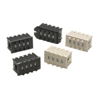
Switches (Single Switch Units)
|
Model |
A7PS |
A7PH |
||
|
Classification |
Snap-in (front mounting) |
Snap-in (front mounting)
|
||
|
Character height |
Decimal: 6.8 mm Hexadecimal: 4.0 mm |
|||
|
Terminals |
Solder terminals |
|||
|
Color |
Light gray |
Black |
Light gray |
Black |
|
Output code number |
Model |
|||
|
03 (decimal code) |
A7PS-203 |
A7PS-203-1 |
A7PH-203 |
A7PH-203-1 |
|
06 (binary coded decimal) |
A7PS-206 |
A7PS-206-1 |
A7PH-206 |
A7PH-206-1 |
|
07 (binary coded decimal, |
A7PS-207 |
A7PS-207-1 |
A7PH-207 |
A7PH-207-1 |
|
19 (decimal code, |
A7PS-219 |
A7PS-219-1 |
--- |
--- |
|
54 (binary coded hexadecimal) |
A7PS-254 |
A7PS-254-1 |
A7PH-254 |
A7PH-254-1 |
|
55 (binary coded hexadecimal, |
A7PS-255 |
A7PS-255-1 |
--- |
--- |


Note: 1. The classification diagrams show 4 Switch Units combined with End Caps to create 4-digit displays.
2. The model numbers given above are for 1 Switch Unit.
3. Models with stoppers are also available. Add "-S[][]" after the "203," "206," "207," "219," "254," or "255" in the model number and specify the display range in the [][]. For example, to specify the range 0 to 6, add "-S06" to the model number (e.g., A7PS-206-S06-1). “-SOF” can not be available for type -254, -255.
4. Models with +, - displays can also be produced. Add "-PM" after the "206" in the model number (e.g., A7PS-206-PM or A7PS-206-PM-1)
*1. Models with diodes are available. Add “-D” to the model number (e.g., A7PS-207-D or A7PS-207-D-1).
Accessories (Order Separately)
Use accessories, such as End Caps and Spacers, with the Switch Units.
|
Color |
Light gray |
Black |
|
|
End Caps |
A7P-M |
A7P-M-1 |
|
|
Spacer |
A7P-P[] |
A7P-P[]-1 |
|
|
Connectors |
Solder terminals |
NRT-C |
|
|
NRT-CN |
|||
|
PCB terminals |
NRT-CP |
||
Note: The [] in the Spacer model number stands for a letter in the range A to U. (Refer to the table in the following explanation about Spacers.)
End Caps
End Caps are used on the Switch Units at each end and allow all the Switch Units to be securely mounted to a panel. They come in pairs, one for the left and one for the right.
Spacers
- Spacers are used for creating extra space or gaps between the Switch Units and have the same dimensions as the Switch Units themselves.
- There are also Spacers with engraved characters or symbols that can be used for indicating units, such as time and length. (Refer to the following table.) Consult your OMRON representative for details.
|
Symbol |
A |
B |
C |
D |
E |
F |
G |
H |
J |
K |
L |
Q |
T |
U |
|
Stamp |
No designation |
SEC |
MIN |
H |
g |
kg |
mm |
cm |
m |
°C |
PCS |
x 10 |
0 |
● |