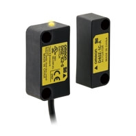
Compact non-contact Door Switch
D40Z
 Supports ISO 13849-1 (PLe/Safety Category 4). Can be used on higher risk level applications by connecting to Safety Controllers.
Ratings and Characteristics
Model | D40Z-1C[] | |
Interlock type | Type 4 (EN ISO 14119) | |
Coding level | Low level coded (EN ISO 14119) | |
Operating characteristics *2 | Operating distance (OFF --> ON) | 5 mm min. *1 |
Operating distance (ON --> OFF) | 15 mm max. *1 | |
Differential travel | 20% or less of operating distance at 23 °C (maximum 2.5 mm) | |
Influence of temperature | 20% or less of operating distance at 23 °C within temperature range of -10 to 65 °C | |
Repeat accuracy | ±10% of operating distance at 23 °C | |
Ambient operating temperature | -10 to 65 °C (with no icing or condensation) | |
Ambient operating humidity | 25% to 85% | |
Insulation resistance (between charged parts and case) | 50 MΩ max. (at 500 VDC) | |
Dielectric strength (between charged parts and case) | 1,000 VAC for 1 min | |
Degree of contamination | 3 | |
Electromagnetic compatibility | IEC/EN 60497-5-3 compliant | |
Vibration resistance | 10 to 55 to 10 Hz (single amplitude: 0.75 mm, double amplitude: 1.5 mm) | |
Shock resistance | 300 m/s2 min. | |
Degree of protection | IP67 | |
Material | PBT resin | |
Mounting method | M4 screws | |
Terminal screw tightening torque | 1 N·m | |
Power supply voltage | 24 V DC +10%/-15% | |
Power consumption *3 | 0.5 W max. | |
Auxiliary monitoring output | Photocoupler output: 24 V DC, load current: 10 mA | |
LED indicators | Actuator not detected (lights in red); error occurred (blinks in red), actuator detected (lights in yellow), actuator detected and Non-contact Door Switch input OFF (blinks in yellow) | |
Connecting cables | 2 m, 5 m | |
Number of connectable switches | 30 max. (wiring length: 100 m max.) *4 | |
Weight | Switch: approx. 175 g, actuator: approx. 20 g (D40Z-1C5) | |
*1. The condition of this distance are that the switch and actuator target marks are on the same axis and the sensing surfaces are exactly parallel condition. OFF to ON distance shows the switch approaching (Point A in the engineering data graph) and ON to OFF distance shows the switch separating away (Point B in the engineering data graph).
*2. For details on response time and operating time, refer to the catalog or manual of a safety controller to be connected.
*3. Power to be provided to the load is not included.
*4. For details, refer to item "Precautions for Correct Use".
*2. For details on response time and operating time, refer to the catalog or manual of a safety controller to be connected.
*3. Power to be provided to the load is not included.
*4. For details, refer to item "Precautions for Correct Use".
Engineering Data
Note: 1. The operating distance is the distance between the switch and actuator sensing surfaces.
2. The graph of detection area indicates shifting to X or Z direction from following condition that the switch and actuator target marks are on the same axis and the sensing surfaces are exactly parallel condition. Dashed lines indate reference value for maximum and minimun oprating distance at abient temperature +23°C. The solid line indicates reference values of the maximum and minimum operating distances.
3. The operating distance may be affected by ambient metal, magnet catches, and temperature.
4. Detection may occur other than on the detection surfaces of the switch and actuator. Before you use the switch and actuator, refer to “Switch and Actuator Operation” on Data Sheet to set the detection surfaces of the switch and actuator face to face.
Influence of ambient temperature
Detection area


