


 The Standard for Photoelectric Sensors with a Secure Track Record of One Million Sold Yearly.
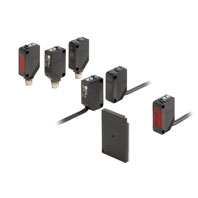
Sensors
|
Sensing |
Appearance |
Connection |
Sensing |
Model |
||
|
NPN output |
PNP output |
|||||
|
Through- |
|
Pre-wired |
15 m |
E3Z-T61 2M *4 *5 |
E3Z-T81 2M *4 *5 |
|
|
Standard M8 |
E3Z-T66 |
E3Z-T86 |
||||
|
Pre-wired |
10 m |
E3Z-T61A 2M *4 |
E3Z-T81A 2M *4M |
|||
|
Standard M8 |
E3Z-T66A |
E3Z-T86A |
||||
|
Pre-wired |
30 m |
E3Z-T62 2M *4 |
E3Z-T82 2M |
|||
|
Standard M8 |
E3Z-T67 |
E3Z-T87 |
||||
|
Retro- |
*1 |
Pre-wired |
4 m |
E3Z-R61 2M *4 *5 |
E3Z-R81 2M *4 *5 |
|
|
Standard M8 |
E3Z-R66 |
E3Z-R86 |
||||
|
Diffuse- |
|
Pre-wired |
5 to 100 mm |
E3Z-D61 2M *4 |
E3Z-D81 2M *4 *5 |
|
|
Standard M8 |
E3Z-D66 |
E3Z-D86 |
||||
|
Pre-wired |
1 m |
E3Z-D62 2M *4 *5 |
E3Z-D82 2M *4 *5 |
|||
|
Standard M8 |
E3Z-D67 |
E3Z-D87 |
||||
|
Pre-wired |
90±30 mm |
E3Z-L61 2M *4 *5 |
E3Z-L81 2M *4 *5 |
|||
|
Standard M8 |
E3Z-L66 |
E3Z-L86 |
||||
|
Distance- |
|
Pre-wired |
20 to 40 mm |
E3Z-LS61 2M *4 |
E3Z-LS81 2M *4 |
|
|
Standard M8 |
E3Z-LS66 |
E3Z-LS86 |
||||
|
Pre-wired |
2 to 20 mm |
E3Z-LS63 2M |
E3Z-LS83 2M *5 |
|||
|
Standard M8 |
E3Z-LS68 |
E3Z-LS88 |
||||
|
Slit-type |
|
1 axis |
Pre-wired |
25 mm |
E3Z-G61 2M *4 *5 |
E3Z-G81 2M *4 *5 |
|
2 |
Pre-wired |
E3Z-G62 2M *4 |
E3Z-G82 2M *4 |
|||
|
1 axis |
Pre-wired |
E3Z-G61-M3J |
E3Z-G81-M3J |
|||
|
2 |
E3Z-G62-M3J |
E3Z-G82-M3J |
||||
|
Limited- |
|
Pre-wired |
30±20 mm |
E3Z-L63 2M |
E3Z-L83 2M |
|
|
Standard M8 |
E3Z-L68 |
E3Z-L88 |
||||
|
Retro- |
*1 |
Pre-wired |
500 mm |
E3Z-B61 2M |
E3Z-B81 2M *4 |
|
|
Standard M8 |
E3Z-B66 |
E3Z-B86 |
||||
|
Pre-wired |
2 m |
E3Z-B62 2M *4 |
E3Z-B82 2M *4 |
|||
|
Standard M8 |
E3Z-B67 |
E3Z-B87 |
||||


1. The Reflector is sold separately. Select the Reflector model most suited to the application.
2. The sensing distance specified is possible when the E39-R1S is used. Values in parentheses indicate the minimum
required distance between the Sensor and Reflector.
3. Through-beam Sensors are normally sold in sets that include both the Emitter and Receiver.
4. M12 Standard Pre-wired Connector Models are also availavble.
When ordering, add "-M1J 0.3M" to the end of the model number (e.g., E3Z-T61-M1J 0.3M).
The cable is 0.3 m long. The applicable Sensor I/O Connector is the XS2 Series. For details, refer to the XS2
information available on the OMRON website.
5. M12 Pre-wired Smartclick Connector Models are also availavble.
When ordering, add "-M1TJ 0.3M" to the end of the model number (e.g., E3Z-T61-M1TJ 0.3M).
The cable is 0.3 m long. The applicable Sensor I/O Connector is the XS5 Series. For details, refer to the XS5
information available on the OMRON website.
Oil-resistive Sensors
|
Sensing |
Appearance |
Connection |
Sensing |
Model |
|
|
NPN output |
PNP output |
||||
|
Through- |
|
Pre-wired |
15 m |
E3Z-T61K 2M *4 |
E3Z-T81K 2M *4 |
|
Pre-wired M8 |
E3Z-T61K-M3J 0.3M |
E3Z-T81K-M3J 0.3M |
|||
|
Retro- |
*1 |
Pre-wired |
3 m |
E3Z-R61K 2M *4 |
E3Z-R81K 2M |
|
Pre-wired M8 |
E3Z-R61K-M3J 0.3M |
E3Z-R81K-M3J 0.3M |
|||
|
Diffuse- |
|
Pre-wired |
5 to 100 mm |
E3Z-D61K 2M *4 |
E3Z-D81K 2M |
|
Pre-wired M8 |
E3Z-D61K-M3J 0.3M |
E3Z-D81K-M3J 0.3M |
|||
|
Pre-wired |
1 m |
E3Z-D62K 2M *4 |
E3Z-D82K 2M |
||
|
Pre-wired M8 |
E3Z-D62K-M3J 0.3M |
E3Z-D82K-M3J 0.3M |
|||


1. The Reflector is sold separately. Select the Reflector model most suited to the application.
2. The sensing distance specified is possible when the E39-R1S is used. Values in parentheses indicate the minimum
required distance between the Sensor and Reflector.
3. Through-beam Sensors are normally sold in sets that include both the Emitter and Receiver.
4. M12 Standard Pre-wired Connector Models are also availavble.
When ordering, add "-M1J 0.3M" to the end of the model number (e.g., E3Z-T61-M1J 0.3M).
The cable is 0.3 m long. The applicable Sensor I/O Connector is the XS2 Series. For details, refer to the XS2
information available on the OMRON website.
Accessories (Order Separately)
Slit
(A Slit is not provided with Through-beam Sensors) Order a Slit separately if required.
|
Slit width |
Sensing distance |
Minimum detectable object |
Model |
Contents |
|
|
E3Z-T[][] |
E3Z-T[][]A |
||||
|
0.5-mm dia. |
50 mm |
35 mm |
0.2-mm dia. |
E39-S65A |
One set |
|
1-mm dia. |
200 mm |
150 mm |
0.4-mm dia. |
E39-S65B |
|
|
2-mm dia. |
800 mm |
550 mm |
0.7-mm dia. |
E39-S65C |
|
|
0.5 × 10 mm |
1 m |
700 mm |
0.2-mm dia. |
E39-S65D |
|
|
1 × 10 mm |
2.2 m |
1.5 m |
0.5-mm dia. |
E39-S65E |
|
|
2 × 10 mm |
5 m |
3.5 m |
0.8-mm dia. |
E39-S65F |
|
Reflectors
(Reflector required for Retroreflective Sensors) A Reflector is not provided with the Sensor. Be sure to order a Reflector separately.
|
Name |
Sensing distance (typical) * |
Model |
Quantity |
Remarks |
||||
|
E3Z-R |
E3Z- |
E3Z- |
E3Z- |
|||||
|
Rated value |
Reference |
Rated |
Rated |
Rated |
||||
|
Reflector |
3 m (100 mm) |
--- |
2 m |
--- |
--- |
E39-R1 |
1 |
Retro- |
|
4 m (100 mm) |
--- |
3 m |
500 mm |
2 m |
E39-R1S |
1 |
||
|
--- |
5 m (100 mm) |
--- |
--- |
--- |
E39-R2 |
1 |
||
|
--- |
2.5 m (100 mm) |
--- |
--- |
--- |
E39-R9 |
1 |
||
|
--- |
3.5 m(100 mm) |
--- |
--- |
--- |
E39-R10 |
1 |
||
|
Fog |
--- |
3 m (100 mm) |
--- |
500 mm |
2 m |
E39-R1K |
1 |
|
|
Small |
--- |
1.5 m (50 mm) |
--- |
--- |
--- |
E39-R3 |
1 |
|
|
Tape |
--- |
700 mm (150 mm) |
--- |
--- |
--- |
E39-RS1 |
1 |
|
|
--- |
1.1 m (150 mm) |
--- |
--- |
--- |
E39-RS2 |
1 |
||
|
--- |
1.4 m (150 mm) |
--- |
--- |
--- |
E39-RS3 |
1 |
||
Note: 1. If you use the Reflector at any distance other than the rated distance, make sure that the stability indicator lights
properly when you install the Sensor.
2. For details, refer to Reflectors on the E39-L/E39-S/E39-R information available on the OMRON website.
* Values in parentheses indicates the minimum required distance between the Sensor and Reflector.
Mutual Interference Protection Filter
A Filter is not provided with the Sensor (for the through-beam E3Z-T[][]A). Order a Filter separately if required.
|
Sensing |
Appearance/ |
Model |
Quantity |
Remarks |
|
3 m |
|
E39-E11 |
Two sets each for |
Can be used with the E3Z-T[][]A Through-beam models. |

Note: The polarization directions of the Filters are offset by 90º to prevent interference. When you install the Emitter and
Receiver, install them at the same angle to maintain this offset.
Mounting Brackets
A Mounting Bracket is not enclosed with the Sensor. Order a Mounting Bracket separately if required.
|
Appearance |
Model |
Quantity |
Remarks |
|
|
E39-L153 |
1 |
Mounting Brackets |
|
|
E39-L104 |
1 |
|
|
|
E39-L43 |
1 |
Horizontal Mounting Brackets |
|
|
E39-L142 |
1 |
Horizontal Protective Cover Bracket |
|
|
E39-L44 |
1 |
Rear Mounting Bracket |
|
|
E39-L98 |
1 |
Metal Protective Cover Bracket |
|
|
E39-L150 |
1 |
(Sensor adjuster) |
|
|
E39-L151 |
1 |
|
|
|
E39-L144 |
1 |
Compact Protective Cover Bracket (For E3Z only) |


Note: 1. When using Through-beam models, order one bracket for the Receiver and one for the Emitter.
2. For details, refer to Mounting Brackets on the E39-L/E39-S/E39-R information available on the OMRON website.
1. Cannot be used for Standard Connector models with mounting surface on the bottom. In that case, use Pre-wired
Connector models.
2. Cannot be used for Standard Connector models.
Sensor I/O Connectors (Sockets on One Cable End)
(Models for Connectors and Pre-wired Connectors: A Connector is not provided with the Sensor. Be sure to order a Connector separately.)
|
Size |
Cable |
Appearance |
Cable type |
Model |
||
|
M8 |
Standard |
Straight *2 |
|
2 m |
4-wire |
XS3F-M421-402-A |
|
5 m |
XS3F-M421-405-A |
|||||
|
L-shaped *2 *3 |
|
2 m |
XS3F-M422-402-A |
|||
|
5 m |
XS3F-M422-405-A |
|||||
|
PUR (Polyurethane) cable *1 |
Straight *2 |
|
2 m |
XS3F-M421-402-L |
||
|
5 m |
XS3F-M421-405-L |
|||||
|
L-shaped *2 *3 |
|
2 m |
XS3F-M422-402-L |
|||
|
5 m |
XS3F-M422-405-L |
|||||
|
Vibration-proof robot cable |
Straight *2 |
|
2 m |
XS3F-M421-402-R |
||
|
5 m |
XS3F-M421-405-R |
|||||
|
L-shaped *2 *3 |
|
2 m |
XS3F-M422-402-R |
|||
|
5 m |
XS3F-M422-405-R |
|||||


Note: 1. When using Through-beam models, order one connector for the Receiver and one for the Emitter.
2. For details, refer to the XS3 information available on the OMRON website.
1. The Sensor can be used in low-temperature environments (−25°C to −40°C). Do not use the Sensor in locations that
are subject to oil.
2. The connector will not rotate after connecting.
3. The cable is fixed at an angle of 180° from the sensor emitter/receiver surface.