


 IO-Link Makes Sensor Level Information Visible and Solves the Three Major Issues at Manufacturing Sites! Standard Photoelectric Sensor.
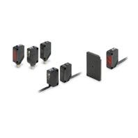
IO-Link Model / Sensors
|
Sensing |
Appearance |
Connection |
Sensing |
IO-Link |
Model |
|
PNP |
|||||
|
Through- |
|
Pre-wired (2 m) |
15 m |
COM2 |
E3Z-T81-IL2 2M |
|
Pre-wired |
E3Z-T81-M1TJ-IL2 0.3M |
||||
|
Standard |
E3Z-T86-IL2 |
||||
|
Pre-wired (2 m) |
COM3 |
E3Z-T81-IL3 2M |
|||
|
Pre-wired |
E3Z-T81-M1TJ-IL3 0.3M |
||||
|
Standard |
E3Z-T86-IL3 |
||||
|
Retro- |
|
Pre-wired (2 m) |
4 m (100 mm) *2 |
COM2 |
E3Z-R81-IL2 2M |
|
Pre-wired |
E3Z-R81-M1TJ-IL2 0.3M |
||||
|
Standard |
E3Z-R86-IL2 |
||||
|
Pre-wired (2 m) |
COM3 |
E3Z-R81-IL3 2M |
|||
|
Pre-wired |
E3Z-R81-M1TJ-IL3 0.3M |
||||
|
Standard M8 |
E3Z-R86-IL3 |
||||
|
Diffuse- |
|
Pre-wired (2 m) |
1 m |
COM2 |
E3Z-D82-IL2 2M |
|
Pre-wired |
E3Z-D82-M1TJ-IL2 0.3M |
||||
|
Standard |
E3Z-D87-IL2 |
||||
|
Pre-wired (2 m) |
COM3 |
E3Z-D82-IL3 2M |
|||
|
Pre-wired |
E3Z-D82-M1TJ-IL3 0.3M |
||||
|
Standard |
E3Z-D87-IL3 |
||||
|
Pre-wired (2 m) |
90 mm |
COM2 |
E3Z-L81-IL2 2M |
||
|
Pre-wired |
E3Z-L81-M1TJ-IL2 0.3M |
||||
|
Standard |
E3Z-L86-IL2 |
||||
|
Pre-wired (2 m) |
COM3 |
E3Z-L81-IL3 2M |
|||
|
Pre-wired |
E3Z-L81-M1TJ-IL3 0.3M |
||||
|
Standard |
E3Z-L86-IL3 |


Note: Please contact your OMRON sales representative regarding the IO-Link setup file (IODD file).
1. The Reflector is sold separately. Select the Reflector model most suited to the application.
2. The sensing distance specified is possible when the E39-R1S is used. Values in parentheses indicate the minimum
required distance between the Sensor and Reflector.
3. Through-beam Sensors are normally sold in sets that include both the Emitter and Receiver.
Accessories (Sold Separately)
Slit
(A Slit is not provided with Through-beam Sensors) Order a Slit separately if required.
|
Slit width |
Sensing distance |
Minimum detectable object |
Model |
Contents |
|
E3Z-T[][] |
||||
|
0.5-mm dia. |
50 mm |
0.2-mm dia. |
E39-S65A |
One set |
|
1-mm dia. |
200 mm |
0.4-mm dia. |
E39-S65B |
|
|
2-mm dia. |
800 mm |
0.7-mm dia. |
E39-S65C |
|
|
0.5 × 10 mm |
1 m |
0.2-mm dia. |
E39-S65D |
|
|
1 × 10 mm |
2.2 m |
0.5-mm dia. |
E39-S65E |
|
|
2 × 10 mm |
5 m |
0.8-mm dia. |
E39-S65F |
Reflectors
(Reflector required for Retroreflective Sensors) A Reflector is not provided with the Sensor. Be sure to order a Reflector separately.
|
Name |
Sensing distance * |
Model |
Quantity |
Remarks |
|
|
E3Z-R |
|||||
|
Rated value |
Reference value |
||||
|
Reflector |
3 m (100 mm) |
--- |
E39-R1 |
1 |
• Reflectors are not provided with |
|
4 m (100 mm) |
--- |
E39-R1S |
1 |
||
|
--- |
5 m (100 mm) |
E39-R2 |
1 |
||
|
--- |
2.5 m (100 mm) |
E39-R9 |
1 |
||
|
--- |
3.5 m(100 mm) |
E39-R10 |
1 |
||
|
Fog Preventive Coating |
--- |
3 m (100 mm) |
E39-R1K |
1 |
|
|
Small Reflector |
--- |
1.5 m (50 mm) |
E39-R3 |
1 |
|
|
Tape Reflector |
--- |
700 mm (150 mm) |
E39-RS1 |
1 |
|
|
--- |
1.1 m (150 mm) |
E39-RS2 |
1 |
||
|
--- |
1.4 m (150 mm) |
E39-RS3 |
1 |
||
Note:1. If you use the Reflector at any distance other than the rated distance, make sure that the stability indicator lights
properly when you install the Sensor.
2. Refer to Reflectors on E39-L/E39-S/E39-R on your OMRON website for details.
* Values in parenthese indicate the minimum required distance between the Sensor and Reflector.
Mounting Brackets
A Mounting Bracket is not enclosed with the Sensor. Order a Mounting Bracket separately if required.
|
Appearance |
Model (material) |
Quantity |
Remarks |
|
|
E39-L153 |
1 |
Mounting Brackets |
|
|
E39-L104 |
1 |
|
|
|
E39-L43 |
1 |
Horizontal Mounting Brackets |
|
|
E39-L142 |
1 |
Horizontal Protective Cover Bracket |
|
|
E39-L44 |
1 |
Rear Mounting Bracket |
|
|
E39-L98 |
1 |
Metal Protective Cover Bracket |
|
|
E39-L150 |
1 |
(Sensor adjuster) |
|
|
E39-L151 |
1 |
|
|
|
E39-L144 |
1 |
Compact Protective |


Note:1. When using Through-beam models, order one bracket for the Receiver and one for the Emitter.
2. Refer to Mounting Brackets on E39-L/E39-S/E39-R on your OMRON website for details.
1. Cannot be used for Standard Connector models with mounting surface on the bottom. In that case, use Pre-wired
Connector models.
2. Cannot be used for Standard Connector models.
Sensor I/O Connectors
(Models for Connectors and Pre-wired Connectors: A Connector is not provided with the Sensor. Be sure to order a Connector separately.)
|
Size |
Type |
Appearance |
Cable length |
Model |
|
|
M12 |
Socket on one cable |
Smartclick connector |
|
2 m |
XS5F-D421-D80-F |
|
5 m |
XS5F-D421-G80-F |
||||
|
Smartclick connector |
|
2 m |
XS5F-D422-D80-F |
||
|
5 m |
XS5F-D422-G80-F |
||||
|
Socket and plug on |
Smartclick connector |
|
2 m |
XS5W-D421-D81-F |
|
|
5 m |
XS5W-D421-G81-F |
||||
|
Smartclick connector |
|
2 m |
XS5W-D422-D81-F |
||
|
5 m |
XS5W-D422-G81-F |
||||
|
M8 |
Socket on one cable |
Straight *3 |
|
2 m |
XS3F-M421-402-A |
|
5 m |
XS3F-M421-405-A |
||||
|
L-shape *3 *4 |
|
2 m |
XS3F-M422-402-A |
||
|
5 m |
XS3F-M422-405-A |
||||
|
M8 socket/ |
Socket and plug on |
M8-M12 (Smartclick) |
|
0.2 m |
XS3W-M42C-4C2-A |


Note:1. When using Through-beam models, order one connector for the Receiver and one for the Emitter.
2. Refer to Sensor I/O Connectors/Sensor Controllers on your OMRON website for details.
1. Straight type/L-shape type combinations are also available.
2. The connectors will not rotate after they are connected.
3. The cable is fixed at an angle of 180° from the sensor emitter/receiver surface.