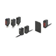
IO-Link Photoelectric Sensor
E3Z-[]-IL[]
 IO-Link Makes Sensor Level Information Visible and Solves the Three Major Issues at Manufacturing Sites! Standard Photoelectric Sensor.
IO-Link Model
|
Sensing method |
Through-beam |
Retro-reflective |
Diffuse- |
Narrow-beam |
||
|
Model |
PNP |
Pre-wired |
E3Z-T81-IL[] |
E3Z-R81-IL[] |
E3Z-D82-IL[] |
E3Z-L81-IL[] |
|
Pre-wired |
E3Z-T81- |
E3Z-R81- |
E3Z-D82- |
E3Z-L81- |
||
|
Connector |
E3Z-T86-IL[] |
E3Z-R86-IL[] |
E3Z-D87-IL[] |
E3Z-L86-IL[] |
||
|
Sensing distance |
15 m |
4 m (100 mm) * |
1 m |
90 + 30 mm |
||
|
Spot diameter |
--- |
2.5 dia. and sensing |
||||
|
Standard sensing object |
Opaque: 12-mm |
Opaque: 75-mm |
--- |
|||
|
Minimum detectable |
--- |
0.1 mm |
||||
|
Differential travel |
--- |
--- |
20% max. of |
Refer to |
||
|
Directional angle |
Both emitter and |
2 to 10° |
--- |
|||
|
Light source (wavelength) |
Infrared LED |
Red LED (660 nm) |
Infrared LED |
Red LED (650 nm) |
||
|
Power supply voltage |
10 to 30 VDC (including 10% ripple (p-p)) |
|||||
|
Current consumption |
50 mA max. |
30 mA max. |
||||
|
Control output |
Load power supply voltage: 30 VDC max., Load current: 100 mA max. |
|||||
|
Indicators |
In the Standard I/O mode (SIO mode): Operation indicator (orange, lit) and stability indicator (green, lit) |
|||||
|
Protection circuits |
Reversed power |
Reversed power supply polarity protection, output short-circuit |
||||
|
Response time |
Operate or reset: 1 ms max. |
|||||
|
Sensitivity adjustment |
Sensitivity adjuster / IO-Link communications |
|||||
|
Ambient illumination |
Incandescent lamp: 3,000 lx max. |
|||||
|
Ambient temperature range |
Operating: -25 to 55°C (with no icing or condensation) |
|||||
|
Ambient humidity range |
Operating: 35% to 85%, Storage: 35% to 95% (with no condensation) |
|||||
|
Insulation resistance |
20 MΩ min. at 500 VDC |
|||||
|
Dielectric strength |
1,000 VAC, 50/60 Hz for 1 min |
|||||
|
Vibration resistance |
Destruction: 10 to 55 Hz, 1.5 mm double amplitude for 2 hours each in X, Y, and Z directions |
|||||
|
Shock resistance |
Destruction: 500 m/s2 3 times each in X, Y, and Z directions |
|||||
|
Degree of protection |
IEC 60529 IP67 |
|||||
|
Connection method |
Pre-wired cable (standard cable length 2 m), M12 pre-wired connector (standard cable length 0.3 m), M8 connector |
|||||
|
Weight |
Pre-wired cable (2 m) |
Approx. 120 g |
Approx. 65 g |
|||
|
Pre-wired connector |
Approx. 60 g |
Approx. 30 g |
||||
|
Connector (M8) |
Approx. 30 g |
Approx. 20 g |
||||
|
Material |
Case |
Polybutylene terephthalate (PBT) |
||||
|
Display |
Modified polyarylate |
|||||
|
Lens |
Modified polyarylate |
Methacrylate resin |
Modified polyarylate |
|||
|
Main IO-Link functions |
Operation mode switching between Light ON and Dark ON, setup of the instability detection level for light receiving and non-light receiving, timer function of the control output and timer time selecting, instability output (IO-Link mode) ON delay timer time selecting, setup of a teaching level and execution of teaching, setup of light receiving sensitivity level, monitor output, operating hours read-out, and initial reset |
|||||
|
Communication |
IO-Link |
Ver 1.1 |
||||
|
Baud rate |
IL3: COM3 (230.4 kbps), -IL2: COM2 (38.4 kbps) |
|||||
|
Data length |
PD size: 2 bytes, OD size: 1 byte (M-sequence type: TYPE_2_2) |
|||||
|
Minimum |
IL3 (COM3): 1 ms, -IL2 (COM2): 2.3 ms |
|||||
|
Accessories |
Instruction manual (Neither Reflectors nor Mounting Brackets are provided with any of the above models.) |
|||||
* Values in parentheses indicate the minimum required distance between the Sensor and Reflector.


