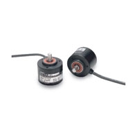
Rugged Incremental 50-mm-dia. Rotary Encoder
E6C3-C
 Rugged Rotary Encoder
|
Model |
E6C3-CWZ5GH |
E6C3-CWZ3EH |
E6C3-CWZ3XH |
|
|
Power supply voltage |
12 VDC -10% to 24 VDC +15%, |
5 VDC -5% to 12 VDC +10%, |
||
|
Current consumption |
100 mA max. |
|||
|
Resolution |
100, 200, 300, 360, 500, 600, 720, 800, 1,000, 1,024, 1,200, 1,500, 1,800, 2,000, 2,048, |
|||
|
Output phases |
Phases A, B, and Z *5 |
|
||
|
Output configuration |
Complementary outputs *2 |
Voltage output (NPN output) |
Line driver output *3 |
|
|
Output capacity |
Output voltage: |
Output resistance: 2 kΩ |
AM26LS31 equivalent |
|
|
Maximum response |
125 kHz (65 kHz when using phase Z reset) |
|||
|
Phase difference |
90°±45° between A and B (1/4 T ± 1/8 T) |
|||
|
Rise and fall times of |
1 μs max. |
1 μs max. |
1 μs max. |
|
|
Starting torque |
10 mNm max. at room temperature, 30 mNm max. at low temperature |
|||
|
Moment of inertia |
2.0 × 10⁻⁶ kgm2 max.; 1.9 × 10⁻⁶ kgm2 max. at 500 P/R max. |
|||
|
Shaft |
Radial |
80 N |
||
|
Thrust |
50 N |
|||
|
Maximum permissible |
5,000 r/min |
|||
|
Protection circuits |
Output load short-circuit protection |
--- |
||
|
Ambient temperature |
Operating: -10 to 70°C (with no icing), Storage: -25 to 85°C (with no icing) |
|||
|
Ambient humidity |
Operating/Storage: 35% to 85% (with no condensation) |
|||
|
Insulation resistance |
20 MΩ min. (at 500 VDC) between current-carrying parts and case |
|||
|
Dielectric strength |
500 VAC, 50/60 Hz for 1 min between current-carrying parts and case |
|||
|
Vibration resistance |
Destruction: 10 to 500 Hz, 150 m/s2 or 2-mm double amplitude for 11 min 3 times each in |
|||
|
Shock resistance |
Destruction: 1,000 m/s2 3 times each in X, Y, and Z directions |
|||
|
Degree of protection |
IEC 60529 IP65, in-house standards: oilproof |
|||
|
Connection method |
Pre-wired Models (Standard cable length: 1 m) |
|||
|
Material |
Case: Aluminum, Main unit: Aluminum, Shaft: SUS303 |
|||
|
Weight (packed state) |
Approx. 300 g |
|||
|
Accessories |
Instruction manual |
|||
1. An inrush current of approximately 9 A will flow for approximately 0.1 ms when the power is turned ON.
2. Complementary Output The complementary output has two output transistors (NPN and PNP) as shown below. These two output transistors alternately turn ON and OFF depending on the high or low output signal. When using them, pull up to the positive
power supply voltage level or pull down to 0 V. The complementary output allows flow-in or flow-out of the output current and thus the rising and falling speeds of signals are fast. This allows a long cable distance. They can be connected to open-collector input devices (NPN, PNP).

3. The line driver output is a data transmission circuit compatible with RS-422A and long-distance transmission is possible with a twisted-pair cable. (AM26LS31 equivalent)
4. The maximum electrical response speed is determined by the resolution and maximum response frequency as follows:

This means that the Rotary Encoder will not operate electrically if its speed exceeds the maximum electrical response speed.
5. The phase Z signal is output when cut face D on the shaft and the cable connection direction are as shown in the following diagram (output position range: ±15°).


