


IoT Flow Sensors
E8FC
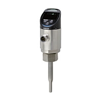 Detect signs of abnormalities in cooling water, water-soluble coolant, and water-insoluble oil by simultaneous measurement of “flow rate + temperature”
Note. For information on the following models, refer to the E8FC-25D/25T/25 series data sheet (Catalog No.E608) listed in the Catalog column.
E8FC-25D/E8FC-25T/E8FC-25
Sensors
|
Model |
NPN/PNP selectable (COM2) |
E8FC-25SD |
|||
|
NPN/PNP selectable (COM3) |
E8FC-25ST |
||||
|
Applicable |
Nominal diameter B |
3/8" |
1/2" |
3/4" |
1" |
|
Nominal diameter A |
10 A |
15 A |
20 A |
25 A |
|
|
Applicable fluid |
The fluid must not corrode the material of the wetted part (e.g. water, |
||||
|
Permissible pressure *1 |
10 MPa |
||||
|
Flow rate |
Rated flow rate range |
0.6 to 14 l/min |
1 to 30 l/min |
1.5 to 60 l/min |
2 to 100 l/min |
|
Inner diameter setting (10 A, 15 A, 20 A, 25 A) |
|||||
|
Display range |
0 to 16 l/min |
0 to 33 l/min |
0 to 66 l/min |
0 to 110 l/min |
|
|
Zero cutting flow rate *3 |
0.6 l/min |
1 l/min |
1.5 l/min |
2 l/min |
|
|
Display resolution |
0.1, 0.5, 1 l/min (Selectable) |
||||
|
Flow rate monitoring |
Control output: 1, 2.5, 5, 10, 30, 60 s |
||||
|
Flow rate monitoring |
± (7.0% of measured value + 2.0% F.S.) or less |
||||
|
Flow rate repeatability |
1 s: ±3.5% F.S., 2.5 s: ±2.5%F.S., 5 s: ±1.6% F.S., 10 s: ±1% F.S., |
||||
|
Ambient temperature |
±1.0% F.S./10°C |
||||
|
Hysteresis |
Variable |
||||
|
Temperature |
Temperature monitoring |
0 to 85°C |
|||
|
Temperature monitoring |
±2.5°C |
||||
|
Temperature repeatability |
±0.5°C |
||||
|
Control |
Standard mode |
It is judged if the measured value is the threshold value or more (or |
|||
|
Window mode |
It is judged if the measured value is within the upper and lower limits. |
||||
|
Display method |
Numerical value indication: 4-digit 7-segment white LED with inverting |
||||
|
Delay setting |
1 to 9999 ms (Select a function from invalid, ON delay, OFF delay, and |
||||
|
Connection method |
M12, 4-pole connector type |
||||
|
Output ch1 |
Control output |
Flow rate control output (N.O./N.C.) /temperature control output (N.O./ |
|||
|
Analog current output *8 |
Flow rate analog output /temperature analog output |
||||
|
Pulse output |
1, 10, 100, 1000 l |
||||
|
Output ch2 |
Control output |
Flow rate control output (N.O./N.C.) /temperature control output (N.O./ |
|||
|
Analog current output *8 |
Flow rate analog output /temperature analog output |
||||
|
Pulse output |
1, 10, 100, 1000 l |
||||
|
External input |
Smart tuning/One-point tuning (selectable, initial status: invalid), |
||||
|
IO-Link |
IO-Link specification |
Ver 1.1 |
|||
|
Baud rate |
E8FC-25SD: COM2 (38.4kbps) |
||||
|
Data length |
PD Size: 6 byte |
||||
|
Minimum cycle time |
E8FC-25SD (COM2): 3.2 ms |
||||
|
Power |
Power supply voltage |
15 to 30 VDC (including 10% ripple (p-p)), Class 2 |
|||
|
Power consumption |
2,880 mW or less |
||||
|
Protection circuit |
Power supply reverse connection protection, output short-circuit |
||||
|
Environment |
Ambient temperature range |
-20 to 70°C in operation and storage, respectively (no condensation) |
|||
|
Applicable fluid temperature |
0 to 85°C (no icing on the pipe surface) |
||||
|
Ambient humidity range |
35 to 85%RH in operation and storage, respectively (no condensation) |
||||
|
Withstand voltage |
500 VAC 50/60 Hz 1 min between charge unit package and case |
||||
|
Vibration resistance |
10 to 2000 Hz, double amplitude 1.5 mm, 2 hours in X/Y/Z direction |
||||
|
Shock resistance |
500 m/s2, three times in X/Y/Z direction each |
||||
|
Protective structure |
IP67 |
||||
|
Materials |
Wetted part |
Detecting unit: SUS304, O-ring: FKM |
|||
|
Other than wetted part |
Head: PPSU, display unit: PES, button: PBT, chassis: SUS304L, nut: |
||||
|
Weight |
Approx. 190 g |
||||
|
Accessories |
• User's manual (Japanese, English, and Chinese), one each |
||||
1. Even instantaneous pressure fluctuation such as water hammer must be within the permissible pressure.
2. Flow monitoring performance is defined by the values measured under the following conditions using OMRON's factory adjustment equipment.
• OMRON's factory adjustment equipment: Pipe diameter 20A, straight pipe length 900 mm or more, recommended pipe joint (KITZ's PTZ-20A), dedicated adapter (E8FC-YA-R20A)
• The long side of the chassis holding unit is installed toward the upstream side of the piping. Refer to Piping method on Catalog.
• Measured normal temperature water (approx. 23°C) under normal temperature environment (approx. 23°C) Since each performance depends on the water level of the piping, there is a possibility that the measured value may deviate depending on the condition that the inside of the piping including the pipe joint is not filled with water, fluid pulsation, and clogging of the piping.
3. Cutting to zero is the function outputting the flow rate less than the minimum rated flow rate as zero.
4. The accuracy of flow rate monitoring when the pipe diameter is 20A. For piping sizes 10A, 15A and 25A, refer to Characteristic Data on Catalog in the catalog before use.
5. The ambient temperature characteristics are defined by the values measured under the following conditions.
• Pipe diameter 20A, Straight pipe length: 900 mm or more, recommended pipe joint (KITZ's PTZ-20A), dedicated adapter (E8FC-YA-R20A)
• The long side of the chassis holding unit is installed toward the upstream side of the piping. Refer to Piping method on Catalog.
• Water at room temperature (approx. 23°C) was measured at a flow rate of 30 l/min.
6. The performance of temperature monitoring is specified by the values measured under the following conditions.
• Pipe diameter 20 A, recommended pipe joint (KITZ's PTZ-20A), dedicated adapter (E8FC-YA-R20A)
• The long side of the chassis holding unit is installed toward the upstream side of the piping. Refer to Piping method on Catalog.
• In a normal temperature environment (approx. 23°C)
7. If the pipe temperature exceeds 70°C, do not contact any cables with the pipe.
8. Do not connect outputs CH1 (pin 4) or/and CH2 (pin 2) with the IO-Link master unit in analog current output mode. Otherwise the IO-Link master might fail.