


Contact-Type Smart Sensor
E9NC-T
 Tough Contact Sensor
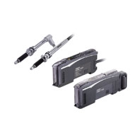
Sensor Heads
|
Type |
Straight type |
E9NC-TH5S |
E9NC-TH12S |
|
|
Right-angle air type |
E9NC-TH5L |
E9NC-TH12L |
||
|
Flanged type/Straight type |
E9NC-TH5SF |
E9NC-TH12SF |
||
|
Flanged type/Right-angle air type |
E9NC-TH5LF |
E9NC-TH12LF |
||
|
Measuring range (Moving range) |
5 mm |
12 mm |
||
|
Resolution |
0.1 μm |
|||
|
Precision *1 |
1 μm |
|||
|
Measuring |
Upward |
0.35±0.25 N |
0.4±0.3 N |
|
|
Horizontal |
0.4±0.25 N |
0.5±0.3 N |
||
|
Downward |
0.45±0.25 N |
0.6±0.3 N |
||
|
Indicator (Preamplifier) |
Operation indicator (blue/red) |
|||
|
Ambient temperature range |
Operating: -10 to 55°C; Storage: -20 to 60°C (with no icing or condensation) |
|||
|
Ambient humidity range |
Operating and storage: 35% to 85% (with no condensation) |
|||
|
Maximum response speed |
80 m/min |
|||
|
Origin detection speed |
80 m/min |
|||
|
Origin position |
1 ±0.5 mm from the spindle push-out position (the lowest point) |
|||
|
Vibration resistance (destruction) |
100 m/s2 (20 to 2,000 Hz) 20 minutes each in X, Y, and Z directions |
|||
|
Shock resistance (destruction) |
1,000 m/s2 3 times each in X, Y, and Z directions |
|||
|
Degree |
Head |
Right-angle air type |
IEC IP67 (only when a hose elbow and air hose are connected) |
|
|
Straight type |
--- |
|||
|
Preamplifier |
--- |
|||
|
Number of sliding operations |
92 million times (based on OMRON’s dedicated evaluation) |
|||
|
Probe |
Carbide with a round surface, screw thread size: M2.5 |
|||
|
Connecting method |
Pre-wired connector (2 m from the Sensor Head to the Preamplifier) |
|||
|
Materials |
Sensor Head |
Stainless steel (SUS303) |
||
|
Rubber boot |
Nitrile rubber (NBR) |
|||
|
Preamplifier |
ABS |
|||
|
Probe contact point *2 |
Carbide |
|||
|
Cable |
PVC |
|||
|
Hose elbow for air (included) |
Nickel-plated brass |
|||
|
Tightening nut, Wave washer |
Tightening nut: Stainless steel (SUS410), Wave washer: SK5 |
|||
|
Weight (packed state/Sensor Head only) |
Approx. 340 g/approx. 110 g |
|||
|
Accessories |
Common: Wrench, Instruction Manual |
|||
1. These values were measured at an ambient temperature of 20°C.
2. For the case of the provided E9NC-TB1 (3-dia. probe)
Amplifier Units
|
Type |
Communications |
ON/OFF output |
|
|
NPN output |
E9NC-TA0 |
E9NC-TA21 |
|
|
PNP output |
E9NC-TA51 |
||
|
Connecting method |
Connector for Sensor |
Pre-wired type |
|
|
Inputs/ |
Outputs |
- *1 |
2 outputs |
|
External inputs |
1 input |
||
|
Power supply voltage |
Supplied from the connector through the |
10 to 30 VDC, including 10% ripple (p-p) |
|
|
Display resolution |
0.1 μm min. |
||
|
Power consumption *2 |
At Power Supply Voltage of 24 VDC |
||
|
Control outputs *3 |
- |
Load power supply voltage: 30 VDC max., |
|
|
External inputs |
- |
Refer to *4. |
|
|
Indicators |
7-segment displays (white) |
||
|
Protection circuits |
Power supply reverse polarity protection |
Power supply reverse polarity protection, |
|
|
Response |
Super-high-speed |
Operate or reset: 3 ms |
|
|
High-speed |
Operate or reset: 10 ms |
||
|
Standard mode |
Operate or reset: 100 ms |
||
|
Giga mode |
Operate or reset: 1,000 ms |
||
|
Threshold setting |
Smart Tuning (2-point area tuning, tolerance tuning, 2-point tuning, 1-point tuning), |
||
|
No. of banks |
4 |
||
|
Functions |
Output mode |
Normal output, hybrid output (Output is performed according to the combination of |
|
|
Preset |
Negative values can be displayed. |
||
|
Resetting |
Select from initial reset (factory defaults) or user reset (saved settings). |
||
|
Eco mode *6 |
Select from OFF (digital display lit), ECO ON (digital display not lit), and |
||
|
Bank switching |
Select from banks 1 to 4. |
||
|
Origin point |
Select whether using the Sensor Head origin point or setting the point at power ON |
||
|
Direction |
Switchable |
||
|
Output |
Select from Normal sensing mode or Area sensing mode. |
||
|
External input |
- |
Select from preset, bank switching, |
|
|
Display digits |
Settable in units ranging from 0.0001 mm to 1 mm. |
||
|
Hysteresis width |
- |
Select from standard setting or user |
|
|
Maximum connectable Units |
With E3NW-ECT: 30 units *7 |
30 units |
|
|
Ambient temperature range |
Operating: Groups of 1 or 2 Amplifier Units: |
Operating: Groups of 1 or 2 Amplifier Units: |
|
|
Ambient humidity range |
Operating and storage: 35% to 85% (with no condensation) |
||
|
Insulation resistance |
20 MΩ (at 500 VDC) |
||
|
Dielectric strength |
1,000 VAC at 50/60 Hz for 1 minute |
||
|
Vibration resistance |
10 to 55 Hz with a 1.5-mm double amplitude for 2 hours each in X, Y, and Z directions |
||
|
Shock resistance |
150 m/s2 for 3 times each in X, Y, |
500 m/s2 for 3 times each in X, Y, |
|
|
Weight (packed state/ |
Approx. 65 g/approx. 25 g |
Approx. 115 g/approx. 75 g |
|
|
Materials |
Case |
Polycarbonate (PC) |
|
|
Cover |
Polycarbonate (PC) |
||
|
Cable |
- |
PVC |
|
|
Accessories |
Instruction Manual |
||
1. Two sensor outputs are allocated in the programmable logic controller (PLC) I/O table.
PLC operation via Communications Unit enables reading detected values and changing settings.
2. At Power Supply Voltage of 10 to 30 VDC. Normal mode: 2,250 mW max. (Current consumption: 75 mA max. at 30 VDC, 155 mA max. at 10 VDC) Eco ON: 2,010 mW max. (Current consumption: 67 mA max. at 30 VDC, 135 mA max. at 10 VDC) Eco LO: 2,130 mW max. (Current consumption: 71 mA max. at 30 VDC, 145 mA max. at 10 VDC)
3. Load current: 20 mA max. in total for the 2 outputs when 4 or more units are linked.
4. The following details apply to the input.
|
Contact input (relay or switch) |
Non-contact input (transistor) |
Input time*4-1 |
|
|
NPN |
ON: Shorted to 0 V (Sourcing current: 1 mA |
ON: 1.5 V max. (Sourcing current: 1 mA max.) |
ON: 9 ms min. |
|
PNP |
ON: Shorted to Vcc (Sinking current: 3 mA |
ON: Vcc - 1.5 V to Vcc (Sinking current: 3 mA |
4-1.Input time is 25 ms (ON)/(OFF) only when (in tUnE) input is selected.
5. The bank is not reset by the user reset function or saved by the user save function.
6. ECO LO is supported for Amplifier Units manufactured in August 2014 or later.
7. When the Sensors are connected to an OMRON NJ-series Controller.