


 Offers Both Durability and Reliability
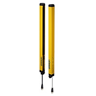
F3SG-RA-01TS
Main Units
Safety Light Curtain
Hand and arm protection
|
Number of beams |
Protective height (mm) |
Model |
|
8 |
185 |
F3SG-4RA0185-25-01TS |
|
12 |
265 |
F3SG-4RA0265-25-01TS |
|
16 |
345 |
F3SG-4RA0345-25-01TS |
|
20 |
425 |
F3SG-4RA0425-25-01TS |
|
24 |
505 |
F3SG-4RA0505-25-01TS |
|
28 |
585 |
F3SG-4RA0585-25-01TS |
|
32 |
665 |
F3SG-4RA0665-25-01TS |
|
36 |
745 |
F3SG-4RA0745-25-01TS |
|
40 |
825 |
F3SG-4RA0825-25-01TS |
|
44 |
905 |
F3SG-4RA0905-25-01TS |
|
48 |
985 |
F3SG-4RA0985-25-01TS |
|
52 |
1,065 |
F3SG-4RA1065-25-01TS |
|
56 |
1,145 |
F3SG-4RA1145-25-01TS |
|
60 |
1,225 |
F3SG-4RA1225-25-01TS |
|
64 |
1,305 |
F3SG-4RA1305-25-01TS |
|
68 |
1,385 |
F3SG-4RA1385-25-01TS |
|
72 |
1,465 |
F3SG-4RA1465-25-01TS |
|
76 |
1,545 |
F3SG-4RA1545-25-01TS |
|
80 |
1,625 |
F3SG-4RA1625-25-01TS |
|
84 |
1,705 |
F3SG-4RA1705-25-01TS |
|
88 |
1,785 |
F3SG-4RA1785-25-01TS |
|
92 |
1,865 |
F3SG-4RA1865-25-01TS |
|
96 |
1,945 |
F3SG-4RA1945-25-01TS |
Accessories (Sold separately)
Safety light curtain connecting cable
Single-Ended Cable (2 cables per set, one for emitter and one for receiver) *
|
Appearance |
Cable length |
Specifications |
Model |
|
|
3m |
|
F39-JD3A |
|
7m |
F39-JD7A |
||
|
10m |
F39-JD10A |
||
|
15m |
F39-JD15A |
||
|
20m |
F39-JD20A |


* The cable for emitter and the cable for receiver are available separately. Add '-L' for emitter or '-D' for receiver to the end of the model number when you order.
Single-Ended Cable for Emitter: F39-JD[]A-L, Single-Ended Cable for Receiver: F39-JD[]A-D
Note: To extend the cable length to more than 20 m, add the F39-JD[]B Double-Ended Cable.
Doble-Ended Cable (2 cables per set, one for emitter and one for receiver) *
For cable extension
|
Appearance |
Cable length |
Specifications |
Model |
|
|
0.5 m |
|
F39-JDR5B |
|
1 m |
F39-JD1B |
||
|
3 m |
F39-JD3B |
||
|
5 m |
F39-JD5B |
||
|
7 m |
F39-JD7B |
||
|
10 m |
F39-JD10B |
||
|
15 m |
F39-JD15B |
||
|
20 m |
F39-JD20B |


* The cable for emitter and the cable for receiver are available separately. Add '-L' for emitter or '-D' for receiver to the end of the model number when you order.
Double-Ended Cable for Emitter: F39-JD(R)[]B-L, Double-Ended Cable for Receiver: F39-JD(R)[]B-D
Note: To extend the cable length to more than 20 m, add the F39-JD[]B Double-Ended Cable to the F39-JD[]A Single- Ended Cable. To extend the cable length to more than 40 m, add several Double-Ended Cables to the Single-Ended Cable.
Example: To extend the cable length to 50 m, connect two F39-JD20B (20 m) cables and one F39-JD10A (10 m) cable.
Connection example

Cascading Cable (2 cables per set, for emitter and receiver)
|
Appearance |
Type |
Cable length |
Specifications |
Model |
|
|
Cap (8-pin), M12 |
0.2m |
|
F39-JGR2WTS |


Note: The Double-Ended Cable (up to 10 m: F39-JD10B) can be added to extend the cable length between the series-connected sensors. Cable length between sensors: 10 m max. (not including cascading cable (F39-JGR2WTS) and power cable)
Connection example

Reduced Wiring Connector System (Order the F39-CN5 and Cables for Reduce Wiring.)
Reduced Wiring Connector
|
Appearance |
Specifications |
Model |
|
|
IP67 rated when mated. |
F39-CN5 |

Note: When using the Reduced Wiring Connector (F39-CN5), the following functions are not available.
- External Device Monitoring
- Auxiliary Output

Cable for Reduce Wiring* (2 cables per set, one for emitter and one for receiver)
|
Appearance |
Cable length |
Specifications |
Remarks |
Model |
|
|
Emitter: 3 m |
IP67 rated |
Double-Ended Cable: F39-JD3B-L |
F39-JD0303BA |
|
Emitter: 3 m |
Double-Ended Cable: F39-JD3B-L |
F39-JD0307BA |
||
|
Emitter: 3 m |
Double-Ended Cable: F39-JD3B-L |
F39-JD0310BA |
||
|
Emitter: 5 m |
Double-Ended Cable: F39-JD5B-L |
F39-JD0503BA |
||
|
Emitter: 5 m |
Double-Ended Cable: F39-JD5B-L |
F39-JD0507BA |
||
|
Emitter: 5 m |
Double-Ended Cable: F39-JD5B-L |
F39-JD0510BA |
||
|
Emitter: 10 m |
Double-Ended Cable: F39-JD10B-L |
F39-JD1003BA |
||
|
Emitter: 10 m |
Double-Ended Cable: F39-JD10B-L |
F39-JD1007BA |
||
|
Emitter: 10 m |
Double-Ended Cable: F39-JD10B-L |
F39-JD1010BA |

Note: A combination of emitter and receiver cables of other lengths than the above is also available. For details, contact your Omron representative.
* Double-Ended Cable for emitter and Single-Ended Cable for receiver.
Sensor Mounting Brackets
|
Appearance |
Specification |
Application |
Model |
|
|
Standard Fixed |
Bracket to mount the F3SG-RA-01TS. |
F39-LGF |
|
|
Standard |
Bracket to mount the F3SG-RA-01TS. |
F39-LGA |
|
|
Top/Bottom |
Bracket to mount the F3SG-RA-01TS. Use this bracket at the |
F39-LGTB |
|
|
Top/Bottom |
Top/Bottom Adjustable Bracket without a bracket to |
F39-LGTB-1 |


*1. Protective height of 0185 to 1225: 2 sets, Protective height of 1305 to 1945: 3 sets
*2. Top/Bottom Adjustable Bracket cannot be used with the Standard Fixed Bracket. Use with the Standard Adjustable
Bracket.
Using Top/Bottom Adjustable Brackets with Standard Adjustable Brackets
Protective height of 1065 or less:
The Standard Adjustable Bracket is not required.
Please purchase 1 set of Top/Bottom Adjustable Brackets (F39-LGTB(-1)).
Protective height of 1145 to 1945:
Please purchase 1 set of Top/Bottom Adjustable Brackets (F39-LGTB(-1)) and 1 set of Standard Adjustable Brackets (F39-LGA).
Interface units and configuration tool SD Manager 2 *
|
Appearance |
Type |
Specifications |
Model |
|
|
SD Manager 2 |
The Configuration Tool SD Manager 2 is |
- |
|
|
Interface Unit |
F39-GIF interface unit to connect the F3SG-RA-01TS |
F39-GIF |
|
|
Bluetooth |
F39-BT bluetooth unit to enable bluetooth on the |
F39-BT |


* The F3SG-RA-01TS provides only the monitoring functionality.
Lamp
|
Appearance |
Type |
Specifications |
Model |
|
|
Lamp unit |
The lamp can be connected to a receiver and turned ON |
F39-LP |
|
Lamp and |
F39-BTLP |

End Cap *
|
Appearance |
Specifications |
Model |
|
|
Housing color: Black |
F39-CNM |

* This accessory can also be used with the F3SG-RA-02TS.
Laser Pointer for F3SG-R
|
Appearance |
Specifications |
Model |
|
|
The laser pointer is attached on the optical surface of the F3SG-R to help coarse |
F39-PTG |

Spatter Protection Cover (2 covers per set, one for emitter and one for receiver)
Spatter Protection Covers include mounting brackets.
|
Appearance |
Safety Light Curtain Model |
Model |
|
Hand protection |
||
|
|
F3SG-4RA0185-25-01TS |
F39-HGA0200 |
|
F3SG-4RA0265-25-01TS |
F39-HGA0280 |
|
|
F3SG-4RA0345-25-01TS |
F39-HGA0360 |
|
|
F3SG-4RA0425-25-01TS |
F39-HGA0440 |
|
|
F3SG-4RA0505-25-01TS |
F39-HGA0520 |
|
|
F3SG-4RA0585-25-01TS |
F39-HGA0600 |
|
|
F3SG-4RA0665-25-01TS |
F39-HGA0680 |
|
|
F3SG-4RA0745-25-01TS |
F39-HGA0760 |
|
|
F3SG-4RA0825-25-01TS |
F39-HGA0840 |
|
|
F3SG-4RA0905-25-01TS |
F39-HGA0920 |
|
|
F3SG-4RA0985-25-01TS |
F39-HGA1000 |
|
|
F3SG-4RA1065-25-01TS |
F39-HGA1080 |
|
|
F3SG-4RA1145-25-01TS |
F39-HGA1160 |
|
|
F3SG-4RA1225-25-01TS |
F39-HGA1240 |
|
|
F3SG-4RA1305-25-01TS |
F39-HGA1320 |
|
|
F3SG-4RA1385-25-01TS |
F39-HGA1400 |
|
|
F3SG-4RA1465-25-01TS |
F39-HGA1480 |
|
|
F3SG-4RA1545-25-01TS |
F39-HGA1560 |
|
|
F3SG-4RA1625-25-01TS |
F39-HGA1640 |
|
|
F3SG-4RA1705-25-01TS |
F39-HGA1720 |
|
|
F3SG-4RA1785-25-01TS |
F39-HGA1800 |
|
|
F3SG-4RA1865-25-01TS |
F39-HGA1880 |
|
|
F3SG-4RA1945-25-01TS |
F39-HGA1960 |

Note:
1. The operating range of the Safety Light Curtain attached with the product is 10% shorter than the rating.
2. The product extends over the DIP Switch cover of the Safety Light Curtain. Be sure to use the product only after all required settings are made to the DIP Switch.
Test Rod
|
Diameter |
Model |
|
25 mm dia. |
F39-TRD25 |
F3SG-RA-02TS
Main Units
Safety Light Curtain
Hand and arm protection
|
Number of beams |
Protective height (mm) |
Model |
|
12 |
240 |
F3SG-4RA0240-25-02TS |
|
16 |
320 |
F3SG-4RA0320-25-02TS |
|
20 |
400 |
F3SG-4RA0400-25-02TS |
|
24 |
480 |
F3SG-4RA0480-25-02TS |
|
28 |
560 |
F3SG-4RA0560-25-02TS |
|
32 |
640 |
F3SG-4RA0640-25-02TS |
|
36 |
720 |
F3SG-4RA0720-25-02TS |
|
40 |
800 |
F3SG-4RA0800-25-02TS |
|
44 |
880 |
F3SG-4RA0880-25-02TS |
|
48 |
960 |
F3SG-4RA0960-25-02TS |
|
52 |
1,040 |
F3SG-4RA1040-25-02TS |
|
56 |
1,120 |
F3SG-4RA1120-25-02TS |
|
60 |
1,200 |
F3SG-4RA1200-25-02TS |
|
64 |
1,280 |
F3SG-4RA1280-25-02TS |
|
68 |
1,360 |
F3SG-4RA1360-25-02TS |
|
72 |
1,440 |
F3SG-4RA1440-25-02TS |
|
76 |
1,520 |
F3SG-4RA1520-25-02TS |
|
80 |
1,600 |
F3SG-4RA1600-25-02TS |
|
84 |
1,680 |
F3SG-4RA1680-25-02TS |
|
88 |
1,760 |
F3SG-4RA1760-25-02TS |
|
92 |
1,840 |
F3SG-4RA1840-25-02TS |
|
96 |
1,920 |
F3SG-4RA1920-25-02TS |
Accessories (Sold separately)
Safety light curtain connecting cable
Single-Ended Cable (Oil-Resistant Cable)
|
Appearance |
Type |
Cable |
Specifications |
Model |
|
|
For emitter |
3m |
|
F39-JD3RA-L |
|
7m |
F39-JD7RA-L |
|||
|
For receiver |
3m |
F39-JD3RA-D |
||
|
7m |
F39-JD7RA-D |


Note: To extend the cable length to more than 7 m, add the F39-JD[]B Double-Ended Cable.
When the Double-Ended Cable is used, protect it from cutting oil.
Single-Ended Cable (2 cables per set, one for emitter and one for receiver) *
|
Appearance |
Cable |
Specifications |
Model |
|
|
3m |
|
F39-JD3A |
|
7m |
F39-JD7A |
||
|
10m |
F39-JD10A |
||
|
15m |
F39-JD15A |
||
|
20m |
F39-JD20A |


* The cable for emitter and the cable for receiver are available separately. Add '-L' for emitter or '-D' for receiver to the end of the model number when you order.
Single-Ended Cable for Emitter: F39-JD[]A-L, Single-Ended Cable for Receiver: F39-JD[]A-D
Note:
1. Use the F39-JD[]RA-L/-D for applications where cutting oil resistance is required.
2. To extend the cable length to more than 20 m, add the F39-JD[]B Double-Ended Cable.
Double-Ended Cable (2 cables per set, one for emitter and one for receiver) *
|
Appearance |
Cable |
Specifications |
Model |
|
|
0.5m |
|
F39-JDR5B |
|
1m |
F39-JD1B |
||
|
3m |
F39-JD3B |
||
|
5m |
F39-JD5B |
||
|
7m |
F39-JD7B |
||
|
10m |
F39-JD10B |
||
|
15m |
F39-JD15B |
||
|
20m |
F39-JD20B |


* The cable for emitter and the cable for receiver are available separately. Add '-L' for emitter or '-D' for receiver to the end of the model number when you order.
Double-Ended Cable for Emitter: F39-JD[]B-L, Double-Ended Cable for Receiver: F39-JD[]B-D
Note: To extend the cable length to more than 20 m, add the F39-JD[]B Double-Ended Cable to the F39-JD[]A Single- Ended Cable. To extend the cable length to more than 40 m, add several Double-Ended Cables to the Single-Ended Cable.
Example: To extend the cable length to 50 m, connect two F39-JD20B (20 m) cables and one F39-JD10A (10 m) cable.
Connection example

Reduced Wiring Connector System (Order the F39-CN5 and Cables for Reduce Wiring.)
Reduced Wiring Connector
|
Appearance |
Specifications |
Model |
|
|
IP67* rated when mated. |
F39-CN5 |

Note: When using the Reduced Wiring Connector (F39-CN5), the following functions are not available.
- External Device Monitoring
- Auxiliary Output

Cable for Reduce Wiring* (2 cables per set, one for emitter and one for receiver
|
Appearance |
Cable length |
Specifications |
Remarks |
Model |
|
|
Emitter: 3 m |
IP67* rated |
Double-Ended Cable: F39-JD3B-L |
F39-JD0303BA |
|
Emitter: 3 m |
Double-Ended Cable: F39-JD3B-L |
F39-JD0307BA |
||
|
Emitter: 3 m |
Double-Ended Cable: F39-JD3B-L |
F39-JD0310BA |
||
|
Emitter: 5 m |
Double-Ended Cable: F39-JD5B-L |
F39-JD0503BA |
||
|
Emitter: 5 m |
Double-Ended Cable: F39-JD5B-L |
F39-JD0507BA |
||
|
Emitter: 5 m |
Double-Ended Cable: F39-JD5B-L |
F39-JD0510BA |
||
|
Emitter: 10 m |
Double-Ended Cable: F39-JD10B-L |
F39-JD1003BA |
||
|
Emitter: 10 m |
Double-Ended Cable: F39-JD10B-L |
F39-JD1007BA |
||
|
Emitter: 10 m |
Double-Ended Cable: F39-JD10B-L |
F39-JD1010BA |

Note: A combination of emitter and receiver cables of other lengths than the above is also available. For details, contact your Omron representative.
* Double-Ended Cable for emitter and Single-Ended Cable for receiver.
Cascading Cable (2 cables per set, one for emitter and one for receiver)
|
Appearance |
Type |
Cable length |
Specifications |
Model |
|
|
Cap (8-pin), M12 |
0.2m |
|
F39-JGR2WTS |


Note: The Double-Ended Cable (up to 10 m: F39-JD10B) can be added to extend the cable length between the series-connected sensors.
Cable length between sensors: 10 m max. (not including cascading cable (F39-JGR2WTS) and power cable)

Sensor Mounting Brackets
|
Appearance |
Specifications |
Application |
Model |
|
|
Free-Location |
Beam alignment after mounting possible. |
F39-LGRA |
|
|
Top/Bottom |
Use this bracket at the top and bottom |
F39-LGRTB |
|
|
Top/Bottom |
The part of this bracket to contact with a wall |
F39-LGRTB-2 |
|
|
Top/Bottom |
F39-LGRTB-3 |


*1. Protective height of 0240 to 1200 mm: 2 sets, Protective height of 1280 to 1920 mm: 3 sets
*2. Use the Top/Bottom Bracket in combination with the Intermediate Bracket.
Protective height of 1040 or less:
The Intermediate Bracket is not required. Please purchase 1 set of Top/Bottom Brackets (F39-LGRTB(-2/-3)).
Protective height of 1120 to 1920:
Please purchase 1 set of Top/Bottom Brackets (F39-LGRTB(-2/-3)) and 1 set of Intermediate Brackets (F39-LGRA).
Interface units and configuration tool SD Manager 2 *1 *2
|
Appearance |
Type |
Specifications |
Model |
|
|
SD Manager 2 |
The Configuration Tool SD Manager 2 is |
- |
|
|
Interface Unit |
F39-GIF-1 interface unit to connect the |
F39-GIF-1 |
|
|
Bluetooth |
F39-BT bluetooth unit to enable bluetooth |
F39-BT |


*1. The F3SG-RA-02TS provides only the monitoring functionality.
*2. When the accessory is used, protect it from cutting oil.
Lamp *
|
Appearance |
Type |
仕様 |
Model |
|
|
Lamp |
The lamp can be connected to a receiver and |
F39-LP |
|
Lamp and |
F39-BTLP |

* When the accessory is used, protect it from cutting oil.
End Cap *1 *2
|
Appearance |
Specifications |
Model |
|
|
Housing color: Black |
F39-CNM |

*1. This accessory can also be used with the F3SG-RA-01TS.
*2. When the accessory is used, protect it from cutting oil.
Laser Pointer for F3SG-R *
|
Appearance |
Specifications |
Model |
|
|
The laser pointer is attached on the optical surface of the F3SG-R to help coarse |
F39-PTG |

* When the accessory is used, protect it from cutting oil.
Test Rod
|
Diameter |
Model |
|
25 mm dia. |
F39-TRD25 |