


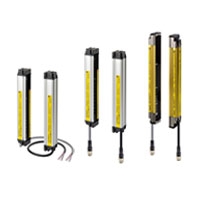
 Three versions available to meet your exact safety needs. All versions conform to the latest PLe/Safety Category 4 and SIL3 requirements.
F3SJ-E
Main Units
F3SJ-E[][][][]P25/N25
|
Model |
PNP output |
F3SJ-E[][][][]P25 |
|
NPN output |
F3SJ-E[][][][]P25 |
|
|
Sensor type |
Type 4 safety light curtain |
|
|
Setting tool connection *1 |
Parameter settings: Not available |
|
|
Safety category |
Safety purpose of category 4, 3, 2, 1, or B |
|
|
Detection capability |
Opaque objects 25 mm in diameter |
|
|
Beam gap (P) |
20 mm |
|
|
Number of beams (n) |
8 to 54 |
|
|
Protective height (PH) |
185 to 1,105 mm |
|
|
Lens diameter |
Diameter 5 mm |
|
|
Operating range *2 |
0.2 to 7 m |
|
|
Response time |
ON to OFF |
15 ms max. |
|
OFF to ON |
70 ms max. |
|
|
Startup waiting time |
2 s max. |
|
|
Power supply voltage (Vs) |
SELV/PELV 24 VDC±20% (ripple p-p 10% max.) |
|
|
Consumption |
PNP output |
Emitter: Up to 22 beams: 41 mA max., 26 to 42 beams: 57 mA max., 46 to 54 beams: |
|
NPN output |
Emitter: Up to 22 beams: 41 mA max., 26 to 42 beams: 57 mA max., 46 to 54 beams: |
|
|
Light source (emitted |
Infrared LED (870 nm) |
|
|
Effective aperture angle |
Based on IEC 61496-2. Within ±2.5° for both emitter and receiver when the |
|
|
Safety outputs |
PNP output |
Two PNP transistor outputs, load current 200 mA max., residual voltage 2 V max. |
|
NPN output |
Two NPN transistor outputs, load current 200 mA max., residual voltage 2 V max. |
|
|
Output operation mode |
Safety output: On when receiving light |
|
|
Input voltage |
PNP output |
Test input: |
|
NPN output |
Test input: |
|
|
Mutual interference |
Mutual interference prevention algorithm prevents interference in up to 3 sets. |
|
|
Test function |
Self test (at power-ON and at power distribution) |
|
|
Protection circuit |
Output short-circuit protection, and power supply reverse polarity protection |
|
|
Ambient temperature |
Operating: -10 to 55°C (non-freezing), Storage: -25 to 70°C |
|
|
Ambient humidity |
Operating: 35% to 85% (no condensation), Storage: 35% to 95% RH |
|
|
Operating ambient light |
Incandescent lamp: 3,000 lx max., Sunlight: 10,000 lx max. |
|
|
Insulation resistance |
20 MΩ min. (at 500 VDC) |
|
|
Dielectric strength |
1,000 VAC 50/60 Hz, 1 min |
|
|
Degree of protection |
IP65 (IEC 60529) |
|
|
Vibration resistance |
Class 3M4 (IEC TR 60721-4-3) |
|
|
Shock resistance |
Class 3M4 (IEC TR 60721-4-3) |
|
|
Pollution degree |
Pollution degree 3 (IEC 60664-1) |
|
|
Power cable |
Connection method: Pull-out type, cable length 3 m |
|
|
Extension cable |
30 m max. *6 |
|
|
Material |
Case: Aluminum |
|
|
Net Weight *7 |
Weight (g) = (protective height) x 1.59 + 330 |
|
|
Gross Weight *8 |
Weight (g) = (protective height) x 2.6 + 800 |
|
|
Accessories |
Instruction Manual, Quick Installation Manual (QIM) *9 |
|
|
Applicable standards *10 |
IEC 61496-1, EN 61496-1, UL 61496-1, Type 4 ESPE (Electro-Sensitive Protective |
|
*1. Do not use the Support Software and Setting Console for F3SJ-A. Operation cannot be guaranteed.
*2. Use of the Spatter Protection Cover causes a 10% maximum sensing distance attenuation.
*3. The load inductance is the maximum value when the safety output frequently repeats ON and OFF. When you use the
safety output at 4 Hz or less, the usable load inductance becomes larger.
*4. These values must be taken into consideration when connecting elements including a capacitive load such as capacitor.
*5. The Vs indicates a voltage value in your environment.
*6. To extend a cable of the F3SJ-E, refer to the User's Manual (SCHG-733/732).
*7. The net weight is the weight of an emitter and a receiver.
*8. The gross weight is the weight of an emitter, a receiver, included accessories and a package.
*9. Mounting brackets and test rod are sold separately.
*10.Refer to Safety Precautions for information about Legislation and Standards.
Indicator
Emitter
|
Nameofindicator |
Label |
ON |
Blinking |
|
Top-beam-state |
TOP |
Turns ON when the top beam is |
--- |
|
Stable-state |
STB |
Turns ON when incidence level is more |
Blinks when the safety output is turned |
|
ON/OFF-state |
ON |
Green: Turns ON when safety output is ON. |
Red: Blinks when the F3SJ-E enters a |
|
Lockout indicator |
LOCKOUT |
Turns ON when the F3SJ-E enters a |
Blinks when the F3SJ-E enters a lockout |
|
Power indicator |
POWER |
Turns ON while the power of the |
Blinks when the F3SJ-E enters a lockout |
|
Test indicator |
TEST |
--- |
Blinks when external test is being |
|
Bottom-beam- |
BTM |
Turns ON when the bottom beam is |
--- |
Receiver
|
Nameofindicator |
Label |
ON |
Blinking |
|
Top-beam-state |
TOP |
Turns ON when the top beam is receiving |
--- |
|
Stable-state |
STB |
Turns ON when incidence level is more |
Blinks when the safety output is turned |
|
ON/OFF-state |
ON |
Green: Turns ON when safety output is ON. |
Red: Blinks when the F3SJ-E enters a |
|
Lockout indicator |
LOCKOUT |
Turns ON when the F3SJ-E enters a |
Blinks when the F3SJ-E enters a lockout |
|
Communication |
COM |
Turns ON when communication between |
Blinks when the F3SJ-E enters lockout |
|
Configuration |
CFG |
--- |
Blinks when the F3SJ-E enters lockout |
|
Internal error |
INTERNAL |
--- |
Blinks when the F3SJ-E enters a lockout |
|
Bottom-beam- |
BTM |
Turns ON when the bottom beam is |
--- |
Accessories
Laser Pointer
|
Model |
F39-PTJ |
|
Applicable sensor |
F3SJ Series |
|
Power supply voltage |
4.65 or 4.5 VDC |
|
Battery |
Three button batteries (SR44 or LR44) |
|
Battery life * |
SR44: 10 hours of continuous operation, LR44: 6 hours of continuous operation |
|
Light source |
Red semiconductor laser (wavelength: 650 nm, 1 mW max. JIS class 2, |
|
Spot diameter (typical value) |
6.5 mm at 10 m |
|
Ambient temperature |
Operating: 0 to 40°C, Storage: -15 to 60°C (with no icing or condensation) |
|
Ambient humidity |
Operating and storage: 35% to 85% (with no condensation) |
|
Material |
Laser module case: aluminum, Mounting bracket: aluminum and stainless |
|
Weight |
Approx. 220 g (packed) |
|
Accessories |
Laser safety standard labels (EN: 1, FDA: 3) Button batteries (SR44: 3), |
* Battery life varies depending on a battery used.
F3SJ-B
Main Units
F3SJ-B[][][][]P25/N25
|
Model |
PNP output |
F3SJ-B[][][][]P25 |
|
NPN output |
F3SJ-B[][][][]N25 |
|
|
Sensor type |
Type 4 safety light curtain |
|
|
Setting tool connection *1 |
Parameter settings: Not available |
|
|
Safety category |
Safety purpose of category 4, 3, 2, 1, or B |
|
|
Detection capability |
Opaque objects 25mm in diameter |
|
|
Beam gap (P) |
20 mm |
|
|
Number of beams (n) |
8 to 102 |
|
|
Protective height (PH) |
185 to 2,065 mm |
|
|
Lens diameter |
Diameter 5 mm |
|
|
Operating range *2 |
0.2 to 7 m |
|
|
Response time |
ON to OFF |
15 ms max. (response time at 1 set connection, series connection of 2 sets or 3 sets) |
|
OFF to ON |
70 ms max. (response time at 1 set connection, series connection of 2 sets or 3 sets) |
|
|
Startup waiting time |
2 s max. |
|
|
Power supply voltage (Vs) |
SELV/PELV 24 VDC±20% (ripple p-p 10% max.) |
|
|
Consumption |
PNP output |
Emitter: Up to 22 beams: 52 mA max., 26 to 42 beams: 68 mA max., 46 to 62 beams: 75 |
|
NPN output |
Emitter: Up to 22 beams: 52 mA max., 26 to 42 beams: 68 mA max., 46 to 62 beams: 75 |
|
|
Light source (emitted |
Infrared LED (870 nm) |
|
|
Effective aperture angle |
Based on IEC 61496-2.Within +/-2.5° for both emitter and receiver when the detection |
|
|
Safety outputs |
PNP output |
Two PNP transistor outputs, load current 200 mA max., residual voltage 2 V max. |
|
NPN output |
Two NPN transistor outputs, load current 200 mA max., residual voltage 2 V max. |
|
|
Auxiliary |
PNP output |
One PNP transistor outputs, load current 100 mA max., residual voltage 2 V max. |
|
NPN output |
One NPN transistor outputs, load current 100 mA max., residual voltage 2 V max. |
|
|
Output operation mode |
Safety output: On when receiving light |
|
|
Input voltage |
PNP output |
Test input, Interlock select input, Reset input, Muting input: |
|
NPN output |
Test input, Interlock select input, Reset input, Muting input: |
|
|
Mutual interference |
Mutual interference prevention algorithm prevents interference in up to 3 sets. |
|
|
Series connection |
Time division emission by series connection |
|
|
Test function |
• Self test (at power-ON and at power distribution) |
|
|
Safety-related functions |
• Interlock (basic system) |
|
|
Connection type |
Connector method (M12, 8-pin) |
|
|
Protection circuit |
Output short-circuit protection, and power supply reverse polarity protection |
|
|
Ambient temperature |
Operating: -10 to 55°C (non-freezing), Storage: -25 to 70°C |
|
|
Ambient humidity |
Operating: 35% to 85% (no condensation), Storage: 35% to 95% RH |
|
|
Operating ambient light |
Incandescent lamp: 3,000 lx max., Sunlight: 10,000 lx max. |
|
|
Insulation resistance |
20 MΩ min. (at 500 VDC) |
|
|
Dielectric strength |
1,000 VAC 50/60 Hz, 1 min |
|
|
Degree of protection |
IP65 (IEC 60529) |
|
|
Vibration resistance |
Class 3M4 (IEC TR 60721-4-3) |
|
|
Shock resistance |
Class 3M4 (IEC TR 60721-4-3) |
|
|
Pollution degree |
Pollution degree 3 (IEC 60664-1) |
|
|
Power cable |
Connection method: Prewired connector cable, cable length 0.3 m, connector type |
|
|
Extension cable |
30 m max. |
|
|
Material |
Case: Aluminum |
|
|
Net Weight *6 |
Weight (g) = (protective height) x 1.62 + 110 |
|
|
Gross Weight *7 |
Weight (g) = (protective height) x 2.7 + 500 |
|
|
Accessories |
Instruction Manual, Quick Installation Manual (QIM) *8 |
|
|
Applicable standards *9 |
IEC 61496-1, EN 61496-1, UL 61496-1, Type 4 ESPE (Electro-Sensitive Protective |
|
*1. Do not use the Support Software and Setting Console for F3SJ-A. Operation cannot be guaranteed.
*2. Use of the Spatter Protection Cover causes a 10% maximum sensing distance attenuation.
*3. The load inductance is the maximum value when the safety output frequently repeats ON and OFF. When you use the
safety output at 4 Hz or less, the usable load inductance becomes larger.
*4. These values must be taken into consideration when connecting elements including a capacitive load such as
capacitor.
*5. The Vs indicates a voltage value in your environment.
*6. The net weight is the weight of an emitter and a receiver.
*7. The gross weight is the weight of an emitter, a receiver, included accessories and a package.
*8. Mounting brackets are sold separately.
*9. Refer to Safety Precautions for information about Legislation and Standards.
Indicator (F3SJ-B[][][][]P25/N25)
Emitter
|
Name of indicator |
Label |
ON |
Blinking |
|
Top-beam-state |
TOP |
Turns ON when the top beam is receiving |
Blinks during muting/override, or when cap |
|
Stable-state |
STB |
Turns ON when incidence level is more |
Blinks when the safety output is turned |
|
ON/OFF-state |
ON |
Green: Turns ON when safety output is |
Red: Blinks when the F3SJ-B enters a |
|
Lockout indicator |
LOCKOUT |
Turns ON when the F3SJ-B enters a |
Blinks when the F3SJ-B enters a lockout |
|
Power indicator |
POWER |
Turns ON while the power of the emitter |
Blinks when the F3SJ-B enters a lockout |
|
Test indicator |
TEST |
--- |
Blinks when external test is being |
|
Muting error |
MUTING |
--- |
Blinks during a muting error. |
|
Muting input 1 |
MUTE1 |
Turns ON when muting input 1 is ON |
--- |
|
Muting input 2 |
MUTE2 |
Turns ON when muting input 2 is ON |
--- |
|
Bottom-beam-state |
BTM |
Turns ON when the bottom beam is |
Blinks during muting/override. |
Receiver
|
Name of indicator |
Label |
ON |
Blinking |
|
Top-beam-state |
TOP |
Turns ON when the top beam is receiving |
Blinks during muting/override, or when |
|
Stable-state indicator |
STB |
Turns ON when incidence level is more |
Blinks when the safety output is turned |
|
ON/OFF-state |
ON |
Green: Turns ON when safety output is |
Red: Blinks when the F3SJ-B enters a |
|
Lockout indicator |
LOCKOUT |
Turns ON when the F3SJ-B enters a |
Blinks when the F3SJ-B enters a lockout |
|
Communication |
COM |
Turns ON when communication between |
Blinks when the F3SJ-B enters lockout |
|
Configuration |
CFG |
--- |
Blinks when the F3SJ-B enters lockout |
|
Internal error |
INTERNAL |
--- |
Blinks when the F3SJ-B enters a lockout |
|
Interlock indicator |
INT |
Turns ON when the F3SJ-B is in interlock |
Blinks when the F3SJ-B enters a lockout |
|
External device |
EDM |
Turns ON when an input is given to |
Blinks when the F3SJ-B enters a lockout |
|
Bottom-beam-state |
BTM |
Turns ON when the bottom beam is |
Blinks during muting/override. |
*1. It turns ON when there is an external device monitoring input regardless of the availability of the external device
monitoring.
*2. The meanings of the indicators are different for the models with the suffix "-01TS". Refer to the F3SJ-B[][][][]P25-01TS
Safety Light Curtain User's Manual (SCHG-734) or the specifications of the models with the suffix "-01TS".
Main Units
F3SJ-B[][][][]P25-01TS/-02TS
|
Model |
F3SJ-B[][][][]P25-01TS |
F3SJ-B[][][][]P25-02TS |
|
|
Sensor type |
Type 4 safety light curtain |
||
|
Setting tool connection *1 |
Parameter settings: Not available |
||
|
Safety category |
Safety purpose of category 4, 3, 2, 1, or B |
||
|
Detection capability |
Opaque objects 25mm in diameter |
||
|
Beam gap (P) |
20 mm |
||
|
Number of beams (n) |
8 to 102 |
10 to 98 |
|
|
Protective height (PH) |
185 to 2,065 mm |
225 to 1,985 mm |
|
|
Lens diameter |
Diameter 5 mm |
||
|
Operating range *2 |
0.2 to 7 m *2 |
0.2 to 6 m |
|
|
Response time |
ON to OFF |
15 ms max. (response time at 1 set connection, series connection of 2 sets or 3 sets) |
|
|
OFF to ON |
70 ms max. (response time at 1 set connection, series connection of 2 sets or 3 sets) |
||
|
Startup waiting time |
2 s max. |
||
|
Power supply voltage (Vs) |
SELV/PELV 24 VDC±20% (ripple p-p 10% max.) |
||
|
Consumption |
Emitter |
Up to 22 beams: 52 mA max., 26 to 42 |
Up to 22 beams: 52 mA max., 26 to 42 |
|
Receiver |
Up to 22 beams: 45 mA max., 26 to 42 |
Up to 22 beams: 45 mA max., 26 to 42 |
|
|
Light source (emitted |
Infrared LED (870 nm) |
||
|
Effective aperture angle |
Based on IEC 61496-2.Within +/-2.5° for both emitter and receiver when the |
||
|
Safety outputs (OSSD) |
Two PNP transistor outputs, load current 200 mA max., residual voltage 2 V max. |
||
|
Auxiliary output |
One PNP transistor outputs, load current 100 mA max., residual voltage 2 V max. |
||
|
Output operation mode |
Safety output: On when receiving light |
Safety output: On when receiving light |
|
|
Input voltage |
Test input |
Test input, Interlock select input, Reset |
|
|
Mutual interference |
Mutual interference prevention algorithm prevents interference in up to 3 sets. |
||
|
Series connection |
Time division emission by series |
Time division emission by series |
|
|
Test function |
• Self test (at power-ON and at power distribution) |
||
|
Safety-related functions |
External device monitoring |
External device monitoring (basic system) |
|
|
Connection type |
Connector method (M12, 8-pin) |
||
|
Protection circuit |
Output short-circuit protection, and power supply reverse polarity protection |
||
|
Ambient temperature |
Operating: -10 to 55°C (non-freezing), Storage: -25 to 70°C |
||
|
Ambient humidity |
Operating: 35% to 85% (no condensation), Storage: 35% to 95% RH |
||
|
Operating ambient light |
Incandescent lamp: 3,000 lx max., Sunlight: 10,000 lx max. |
||
|
Insulation resistance |
20 MΩ min. (at 500 VDC) |
||
|
Dielectric strength |
1,000 VAC 50/60 Hz, 1 min |
||
|
Degree of protection |
IP65 (IEC 60529) |
||
|
Vibration resistance |
Class 3M4 (IEC TR 60721-4-3) |
||
|
Shock resistance |
Class 3M4 (IEC TR 60721-4-3) |
||
|
Pollution degree |
Pollution degree 3 (IEC 60664-1) |
||
|
Power cable |
Connection method: Prewired connector cable, cable length 0.3 m, connector type (M12, |
||
|
Extension cable |
30 m max. |
||
|
Material |
Case: Aluminum |
||
|
Net Weight *6 |
Weight (g) = (protective height) x 1.62 + |
Weight (g) = (protective height) x 1.83 + |
|
|
Gross Weight *7 |
Weight (g) = (protective height) x 2.7 + 500 |
Weight (g) = (protective height) x 2.9 + 550 |
|
|
Accessories |
Quick Installation Manual (QIM), Instruction Manual *8 |
||
|
Applicable standards *9 |
IEC 61496-1, EN 61496-1, UL 61496-1, Type 4 ESPE (Electro-Sensitive Protective |
||
Note: 1. The test input logic of the models with the suffix "-01TS" is inverted. Refer to the F3SJ-B[][][][]P25-01TS Safety
Light Curtain User's Manual (SCHG-734) for details.
2. Reset mode is fixed with auto reset mode.
*1. Do not use the Support Software and Setting Console for F3SJ-A. Operation cannot be guaranteed.
*2. Use of the Spatter Protection Cover causes a 10% maximum sensing distance attenuation.
*3. The load inductance is the maximum value when the safety output frequently repeats ON and OFF. When you use the
safety output at 4 Hz or less, the usable load inductance becomes larger.
*4. These values must be taken into consideration when connecting elements including a capacitive load such as
capacitor.
*5. The Vs indicates a voltage value in your environment.
*6. The net weight is the weight of an emitter and a receiver.
*7. The gross weight is the weight of an emitter, a receiver, included accessories and a package.
*8. Mounting brackets and test rod are sold separately.
*9. Refer to Safety Precautions for information about Legislation and Standards.
Indicator (F3SJ-B[][][][]P25-01TS)
Emitter
|
Name of indicator |
Label |
ON |
Blinking |
|
Top-beam-state |
TOP |
Turns ON when the top beam is receiving |
Blinks when cap error or connection error |
|
Stable-state |
STB |
Turns ON when incidence level is 170% or |
Blinks when the safety output is turned |
|
ON/OFF-state |
ON |
Green: Turns ON when safety output is |
Red: Blinks when the F3SJ-B enters a |
|
Lockout indicator |
LOCKOUT |
Turns ON when the F3SJ-B enters a |
Blinks when the F3SJ-B enters a lockout |
|
Power indicator |
POWER |
Turns ON while the power of the emitter |
Blinks when the F3SJ-B enters a lockout |
|
Test indicator |
TEST |
--- |
Blinks when external test is being |
|
Bottom-beam-state |
BTM |
Turns ON when the bottom beam is |
--- |
Receiver
|
Name of indicator |
Label |
ON |
Blinking |
|
Top-beam-state |
TOP |
Turns ON when the top beam is receiving |
Blinks when cap error or connection error |
|
Stable-state indicator |
STB |
Turns ON when incidence level is 170% |
Blinks when the safety output is turned |
|
ON/OFF-state |
ON |
Green: Turns ON when safety output is |
Red: Blinks when the F3SJ-B enters a |
|
Lockout indicator |
LOCKOUT |
Turns ON when the F3SJ-B enters a |
Blinks when the F3SJ-B enters a lockout |
|
Communication |
COM |
Turns ON when communication between |
Blinks when the F3SJ-B enters lockout |
|
Configuration |
CFG |
--- |
Blinks when the F3SJ-B enters lockout |
|
Internal error |
INTERNAL |
--- |
Blinks when the F3SJ-B enters a lockout |
|
Interlock indicator |
INT |
Not used |
Not used |
|
External device |
EDM |
Turns ON when an input is given to |
Blinks when the F3SJ-B enters a lockout |
|
Bottom-beam-state |
BTM |
Turns ON when the bottom beam is |
--- |
* It turns ON when there is an external device monitoring input regardless of the availability of the external device monitoring.
Indicator (F3SJ-B[][][][]P25-02TS)
Emitter
|
Name of indicator |
Label |
ON |
Blinking |
|
Top-beam-state |
TOP |
Turns ON when the top beam is receiving |
Blinks during muting/override, or when |
|
Stable-state indicator |
STB |
Turns ON when incidence level is 170% |
Blinks when the safety output is turned |
|
ON/OFF-state |
ON |
Green: Turns ON when safety output is |
Red: Blinks when the F3SJ-B enters a |
|
Lockout indicator |
LOCKOUT |
Turns ON when the F3SJ-B enters a |
Blinks when the F3SJ-B enters a lockout |
|
Power indicator |
POWER |
Turns ON while the power of the emitter |
Blinks when the F3SJ-B enters a lockout |
|
Test indicator |
TEST |
--- |
Blinks when external test is being |
|
Muting error indicator |
MUTING |
--- |
Blinks during a muting error. |
|
Muting input 1 |
MUTE1 |
Turns ON when muting input 1 is ON |
--- |
|
Muting input 2 |
MUTE2 |
Turns ON when muting input 2 is ON |
--- |
|
Bottom-beam-state |
BTM |
Turns ON when the bottom beam is |
Blinks during muting/override. |
Receiver
|
Name of indicator |
Label |
ON |
Blinking |
|
Top-beam-state |
TOP |
Turns ON when the top beam is receiving |
Blinks during muting/override, or when |
|
Stable-state indicator |
STB |
Turns ON when incidence level is 170% |
Blinks when the safety output is turned |
|
ON/OFF-state |
ON |
Green: Turns ON when safety output is |
Red: Blinks when the F3SJ-B enters a |
|
Lockout indicator |
LOCKOUT |
Turns ON when the F3SJ-B enters a |
Blinks when the F3SJ-B enters a lockout |
|
Communication |
COM |
Turns ON when communication between |
Blinks when the F3SJ-B enters lockout |
|
Configuration |
CFG |
--- |
Blinks when the F3SJ-B enters lockout |
|
Internal error |
INTERNAL |
--- |
Blinks when the F3SJ-B enters a lockout |
|
Interlock indicator |
INT |
Not used |
Not used |
|
External device |
EDM |
Turns ON when an input is given to |
Blinks when the F3SJ-B enters a lockout |
|
Bottom-beam-state |
BTM |
Turns ON when the bottom beam is |
Blinks during muting/override. |
* It turns ON when there is an external device monitoring input regardless of the availability of the external device monitoring.
Accessories
Control Unit
|
Model |
F3SP-B1P |
|
|
Applicable sensor |
F3SJ-B/A (Only for PNP output type) * |
|
|
Power supply voltage |
24 VDC±10% |
|
|
Power consumption |
DC1.7 W max. (not including sensor's current consumption) |
|
|
Operation time |
100 ms max. (not including sensor's response time) |
|
|
Response time |
100 ms max. (not including sensor's response time) |
|
|
Relay output |
Number of contacts |
3NO+1NC |
|
Rated load |
25 VAC 5 A (cos ϕ = 1), 30 VDC 5 A L/R = 0 ms |
|
|
Rated current |
5 A |
|
|
Connection type |
Between sensors |
M12 connector (8-pin) |
|
Others |
Terminal block |
|
|
Weight (packed state) |
Approx. 280 g |
|
|
Accessories |
Instruction manual |
|
* NPN output type cannot be connected. Also, the system cannot be used as a muting system.
Laser Pointer
|
Model |
F39-PTJ |
|
Applicable sensor |
F3SJ Series *1 |
|
Power supply voltage |
4.65 or 4.5 VDC |
|
Battery |
Three button batteries (SR44 or LR44) |
|
Battery life *2 |
SR44: 10 hours of continuous operation, LR44: 6 hours of continuous operation |
|
Light source |
Red semiconductor laser (wavelength: 650 nm, 1 mW max. JIS class 2, |
|
Spot diameter (typical value) |
6.5 mm at 10 m |
|
Ambient temperature |
Operating: 0 to 40°C Storage: -15 to 60°C (with no icing or condensation) |
|
Ambient humidity |
Operating and storage: 35% to 85% (with no condensation) |
|
Material |
Laser module case: aluminum Mounting bracket: aluminum and stainless |
|
Weight |
Approx. 220 g (packed) |
|
Accessories |
Laser safety standard labels (EN: 1, FDA: 3) Button batteries (SR44: 3), |
*1. It cannot be mounted to the models with the suffix "-02TS".
*2. Battery life varies depending on a battery used.
F3SJ-A
Main Units
F3SJ-A[][][][]P14/P20/P30/P55/N14/N20/N30/N55
|
Model |
PNP |
F3SJ-A[][][][]P14 |
F3SJ-A[][][][]P20 |
F3SJ-A[][][][]P30 |
F3SJ-A[][][][]P55 |
|
NPN |
F3SJ-A[][][][]N14 |
F3SJ-A[][][][]N20 |
F3SJ-A[][][][]N30 |
F3SJ-A[][][][]N55 |
|
|
Sensor type |
Type 4 safety light curtain |
||||
|
Version |
Ver. 2 |
||||
|
Setting tool connection |
Connectable |
||||
|
Safety category |
Safety purpose of category 4, 3, 2, 1, or B |
||||
|
Detection capability |
Opaque objects |
Opaque objects |
Opaque objects |
Opaque objects |
|
|
Beam gap (P) |
9 mm |
15 mm |
25 mm |
50 mm |
|
|
Number of beams (n) |
26 to 140 |
16 to 100 |
10 to 100 |
6 to 50 |
|
|
Protective height (PH) |
245 to 1,271 mm |
245 to 1,505 mm |
245 to 2,495 mm |
270 to 2,470 mm |
|
|
Lens diameter |
Diameter 5 mm |
||||
|
Operating range * |
0.2 to 9 m (protective height 1,640 mm max.), 0.2 to 7 m (protective height 1,655 mm min.) |
||||
|
Response |
ON to OFF |
1 set, |
1 set, |
1 set: 10 ms to |
1 set: 10 ms to |
|
OFF to ON |
1 set, |
1 set, |
1 set: 40 ms to |
1 set: 40 ms to |
|
|
Startup waiting time |
2 s max. (2.2 s max. for series connection) |
||||
|
Power supply voltage (Vs) |
24 VDC ±20% (ripple p-p10% max.) |
||||
|
Current |
Emitter |
To 50 beams: 76 mA max., 51 to 100 beams: 106 mA max., 101 to 150 beams: 130 mA |
|||
|
Receiver |
To 50 beams: 68 mA max., 51 to 100 beams: 90 mA max., 101 to 150 beams: 111 mA |
||||
|
Light source (emitted |
Infrared LED (870 nm) |
||||
|
Effective aperture angle |
Based on IEC 61496-2. Within ±2.5° for both emitter and receiver when the detection |
||||
|
Safety |
PNP |
Two PNP transistor outputs, load current 300 mA max., residual voltage 2 V max. (except |
|||
|
NPN |
Two NPN transistor outputs, load current 300 mA max., residual voltage 2 V max. (except |
||||
|
Auxiliary |
PNP |
One PNP transistor output, load current 300 mA max., residual voltage 2 V max. (except |
|||
|
NPN |
One NPN transistor output, load current 300 mA max., residual voltage 2 V max. (except |
||||
|
Auxiliary |
PNP |
One PNP transistor output, load current 50 mA max., residual voltage 2 V max. (except |
|||
|
NPN |
One NPN transistor output, load current 50 mA max., residual voltage 2 V max. (except |
||||
|
External indicator output |
Available indicators |
||||
|
Output |
Receiver |
Safety output 1, 2: ON when receiving light |
|||
|
Emitter |
Auxiliary output 2: Turns ON when the point of 30,000 operating hours is reached |
||||
|
Input |
PNP |
Test input, Interlock select input, Reset input, Muting input: |
|||
|
NPN |
Test input, Interlock select input, Reset input, Muting input: |
||||
|
Indicator |
Emitter |
Light intensity level indicators (green LED x 2, orange LED x 3): ON based on the light |
|||
|
Receiver |
Light intensity level indicators (green LED x 2, orange LED x 3): ON based on the light |
||||
|
Mutual interference |
Interference light prevention algorithm, detection distance change function |
||||
|
Series connection |
Time division emission by series connection |
||||
|
Test function |
• Self test (at power-ON and at power distribution) |
||||
|
Safety-related functions |
• Start interlock, restart interlock (Must be set with a setting tool when the muting function is used.) |
||||
|
Connection method |
Connector method (M12, 8-pin) |
||||
|
Protective circuits |
Output short-circuit protection, and power supply reverse polarity protection |
||||
|
Ambient temperature |
Operating: -10 to 55°C (no icing), Storage: -30 to 70°C |
||||
|
Ambient humidity |
Operating: 35% to 85% (no condensation), Storage: 35% to 95% |
||||
|
Operating ambient light |
Incandescent lamp: receiving-surface light intensity of 3,000 lx max., Sunlight: receiving- |
||||
|
Insulation resistance |
20 MΩ min. (at 500 VDC) |
||||
|
Withstand voltage |
1,000 VAC 50/60 Hz, 1 min |
||||
|
Degree of protection |
IP65 (IEC 60529) |
||||
|
Vibration resistance |
Class 3M4 (IEC TR 60721-4-3) |
||||
|
Shock resistance |
Class 3M4 (IEC TR 60721-4-3) |
||||
|
Materials |
Casing (including metal parts on both ends): Aluminum, zinc die-cast |
||||
|
Net Weight *1 |
Calculate using the following expressions: |
||||
|
Gross Weight *1 |
Calculate using the following expressions: |
||||
|
Accessories |
Instruction manual, standard mounting bracket (F39-LJ1 bracket for top/bottom |
||||
|
Applicable standards *3 |
IEC 61496-1, EN 61496-1, UL 61496-1, Type 4 ESPE (Electro-Sensitive Protective |
||||
* Use of the Spatter Protection Cover causes a 10% maximum sensing distance attenuation.
*1. The net weight is the weight of an emitter and a receiver.
*2. The gross weight is the weight of an emitter, a receiver, included accessories and a package.
*3. Refer to Safety Precautions for information about Legislation and Standards.
Response Time
|
Model |
Protected Height |
Number of Beams |
Response time ms |
Response time ms |
|
F3SJ-A[]14 Series |
245 to 263 |
26 to 28 |
11 |
44 |
|
281 to 389 |
30 to 42 |
12 |
48 |
|
|
407 to 497 |
44 to 54 |
13 |
52 |
|
|
515 to 605 |
56 to 66 |
14 |
56 |
|
|
623 to 731 |
68 to 80 |
15 |
60 |
|
|
767 to 983 |
84 to 108 |
17.5 |
70 |
|
|
1,055 to 1,271 |
116 to 140 |
20 |
80 |
|
|
F3SJ-A[]20 Series |
245 |
16 |
10 |
40 |
|
275 to 425 |
18 to 28 |
11 |
44 |
|
|
455 to 635 |
30 to 42 |
12 |
48 |
|
|
665 to 815 |
44 to 54 |
13 |
52 |
|
|
845 to 995 |
56 to 66 |
14 |
56 |
|
|
1,025 to 1,205 |
68 to 80 |
15 |
60 |
|
|
1,235 to 1,505 |
82 to 100 |
17.5 |
70 |
|
|
F3SJ-A[]30 Series |
245 to 395 |
10 to 16 |
10 |
40 |
|
420 to 720 |
17 to 29 |
11 |
44 |
|
|
745 to 1,045 |
30 to 42 |
12 |
48 |
|
|
1,070 to 1,295 |
43 to 52 |
13 |
52 |
|
|
1,395 to 1,620 |
56 to 65 |
14 |
56 |
|
|
1,745 to 1,995 |
70 to 80 |
15 |
60 |
|
|
2,120 to 2,495 |
85 to 100 |
17.5 |
70 |
|
|
F3SJ-A[]55 Series |
270 to 770 |
6 to 16 |
10 |
40 |
|
820 to 1,420 |
17 to 29 |
11 |
44 |
|
|
1,470 to 2,070 |
30 to 42 |
12 |
48 |
|
|
2,120 to 2,470 |
43 to 50 |
13 |
52 |
Note:
Use the following expressions for series connection.
For 2-set series connection:
Response time (ON to OFF): Response time of the 1st unit + Response time of the 2nd unit - 1 (ms), Response time (OFF
to ON): Response time calculated by the above x 4 (ms)
For 3-set series connection:
Response time (ON to OFF):
Response time of the 1st unit + Response time of the 2nd unit + Response time of 3rd unit - 5 (ms), Response time (OFF
to ON): Response time calculated by the above x 5 (ms)
(For models with the "-TS" suffix, multiply the response time obtained by the above x 5 (ms), or use 200 ms, whichever
is less.)
For 4-set series connection:
Response time (ON to OFF): Response time of the 1st unit + Response time of the 2nd unit + Response time of the 3rd
unit + Response time of the 4th unit - 8 (ms)
Response time (OFF to ON): Response time calculated by the above x 5 (ms)
Cable Extension Length
Total cable extension length must be no greater than the lengths described below.
When the F3SJ and an external power supply are directly connected, or when the F3SJ is connected to a G9SA-300-SC.
|
Condition |
1 set |
2 sets |
3 sets |
4 sets |
|
Using incandescent lamp for auxiliary output and external indicator output |
45 m |
40 m |
30 m |
20 m |
|
Not using incandescent lamp * |
100 m |
60 m |
45 m |
30 m |
When connected to the F3SP-B1P
|
Condition |
1 set |
2 sets |
3 sets |
4 sets |
|
Using incandescent lamp for external indicator output 2 |
40 m |
30 m |
25 m |
20 m |
|
Using incandescent lamp for external indicator output 1 |
60 m |
45 m |
30 m |
20 m |
|
Using incandescent lamp for auxiliary output 1 |
||||
|
Not using incandescent lamp * |
100 m |
60 m |
45 m |
30 m |
Note: Keep the cable length within the rated length. Failure to do so is dangerous as it may prevent safety functions from
operating normally.
* The F39-A01P[]-PAC Dedicated External Indicator Set uses LEDs. Refer to the cable extension lengths for "Not using
incandescent lamp".
Accessories
Control Unit
|
Model |
F3SP-B1P |
|
|
Applicable sensor |
F3SJ-B/A (Only for PNP output type) * |
|
|
Power supply voltage |
24 VDC±10% |
|
|
Power consumption |
DC1.7 W max. (not including sensor's current consumption) |
|
|
Operation time |
100 ms max. (not including sensor's response time) |
|
|
Response time |
10 ms max. (not including sensor's response time) |
|
|
Relay output |
Number of contacts |
3NO+1NC |
|
Rated load |
25 VAC 5 A (cos ϕ = 1), 30 VDC 5 A L/R = 0 ms |
|
|
Rated current |
5 A |
|
|
Connection type |
Between sensors |
M12 connector (8-pin) |
|
Others |
Terminal block |
|
|
Weight (packed state) |
Approx. 280 g |
|
|
Accessories |
Instruction manual |
|
* NPN output type cannot be connected. Also, the system cannot be used as a muting system.
Laser Pointer
|
Model |
F39-PTJ |
|
Applicable sensor |
F3SJ Series |
|
Power supply voltage |
4.65 or 4.5 VDC |
|
Battery |
Three button batteries (SR44 or LR44) |
|
Battery life * |
SR44: 10 hours of continuous operation, LR44: 6 hours of continuous operation |
|
Light source |
Red semiconductor laser (wavelength: 650 nm, 1 mW max. JIS class 2, |
|
Spot diameter (typical value) |
6.5 mm at 10 m |
|
Ambient temperature |
Operating: 0 to 40°C Storage: -15 to 60°C (with no icing or condensation) |
|
Ambient humidity |
Operating and storage: 35% to 85% (with no condensation) |
|
Material |
Laser module case: aluminum Mounting bracket: aluminum and stainless |
|
Weight |
Approx. 220 g (packed) |
|
Accessories |
Laser safety standard labels (EN: 1, FDA: 3) Button batteries (SR44: 3), |
* Battery life varies depending on a battery used.
Dedicated External Indicator Set
|
Model |
F39-A01PR-PAC |
F39-A01PG-PAC |
F39-A01PY-PAC |
|
Applicable sensor |
F3SJ-A (Common for PNP/NPN output type. Can be attached to emitters and/or receivers) |
||
|
Light source |
Red LED |
Green LED |
Yellow LED |
|
Power supply voltage |
24 VDC±10% (supplied by sensor) |
||
|
Consumption current |
50 mA max. (supplied by sensor) |
||
|
Connection type |
Dedicated accessory connector cable (Sensor side: Dedicated 10-pin connector, |
||
|
Set details |
Indicator (red), |
Indicator (green), |
Indicator (yellow), |
Water-resistant Case
|
Model |
F39-EJ[][][][]-L, F39-EJ[][][][]-D |
|
|
Applicable sensor |
F3SJ-A Series Curtains with a protective |
F3SJ-A Series Curtains with a protective |
|
Ambient temperature |
-10 to 55°C (operation and storage) |
13 to 33°C (operation and storage) |
|
Mounting direction |
No restrictions |
Vertical direction only (see following diagram) |
|
Operating range |
0.2 to 7 m (for a protective height of 1,631 mm max.), 0.2 to 5 m (for a protective height |
|
|
Degree of protection |
IP67 (IEC 60529) (When assembled according to the application precautions) |
|
|
Material |
Case: Acrylic resin, Rubber: Nitrile rubber, M5 bolt: SUSXM7, M4 bolt: SUS316L, |
|
|
Weight (packed state) |
Calculation formula: Weight (g) = 1.5 x [][][][] + 300 ([][][][] stands for the four digits of the |
|
Note: 1. Vibration
When using Curtains with a protective height of 605 mm or more, the vibration performance of the applicable
sensor is reduced.
Do not use these Curtains in locations that are subject to vibration.
2. Operating range
When using these cases, the operating range of the applicable sensor is reduced.
Check the specifications prior to use.
3. Mounting direction
When using Curtains with a protective height of 605 mm or more, some slackness occurs due to the weight
of the Curtain.
For this reason, mount these Curtains only in the vertical direction.
Mounting direction (the cable end and terminating end can be positioned in either direction)
