


 Compact, Slim Relays Conforming to EN Standards
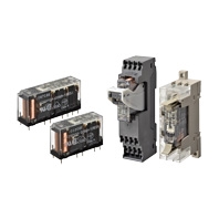
Main unit
Relays with Forcibly Guided Contacts
Specify the coil rated voltage when ordering.
Terminal type | Sealing | Poles | Contact configuration | Coil rated voltage | Model |
PCB terminals | Flux-tight | 4 poles | 3PST-NO, SPST-NC | 12, 18, 21, 24, 48, 110 VDC | G7SA-3A1B |
DPST-NO, DPST-NC | 12, 18, 21, 24, 48, 110 VDC | G7SA-2A2B | |||
6 poles | 5PST-NO, SPST-NC | 12, 18, 21, 24, 48, 110 VDC | G7SA-5A1B | ||
4PST-NO, DPST-NC | 12, 18, 21, 24, 48, 110 VDC | G7SA-4A2B | |||
3PST-NO, 3PST-NC | 12, 18, 21, 24, 48, 110 VDC | G7SA-3A3B |
Options (order separately)
Sockets
Mounting | Terminal Type | LED Indicator | Poles | Coil rated voltage | Appearance | Model |
Front-mounting | Push-In Plus terminals | Yes | 4 poles | 24 VDC |  | P7SA-10F-ND-PU DC24 |
6 poles |  | P7SA-14F-ND-PU DC24 | ||||
Screw terminals | Yes | 4 poles |  | P7SA-10F-ND DC24 | ||
6 poles |  | P7SA-14F-ND DC24 | ||||
No | 4 poles | - |  | P7SA-10F | ||
6 poles |  | P7SA-14F | ||||
Back-mounting | PCB terminals | No | 4 poles | - |  | P7SA-10P |
6 poles |  | P7SA-14P |
Socket Accessories
Short Bars (For P7SA-[]F-ND-PU)
Pitch | No. of poles | Colors | Model*1*2 |
5.2 mm | 2 | Red (RD) Blue (BL) Yellow (YL) | XW5S-P2.5-2[] |
3 | XW5S-P2.5-3[] | ||
4 | XW5S-P2.5-4[] | ||
5 | XW5S-P2.5-5[] |
Note: Use for crossover wiring of adjacent contact terminals (bottom) within one Socket.
*1. Replace the box ([]) in the model number with the code for the covering color.
Color Options: RD = red, BL = blue, YL = yellow
Example: XW5S-P2.5-10RD when the covering color is red.
*2. XW5S-P2.5-5[] cannot be used with P7SA-10F-ND-PU.
*1. Replace the box ([]) in the model number with the code for the covering color.
Color Options: RD = red, BL = blue, YL = yellow
Example: XW5S-P2.5-10RD when the covering color is red.
*2. XW5S-P2.5-5[] cannot be used with P7SA-10F-ND-PU.
Parts for DIN Track Mounting
Type | Model | Minimum Order (quantity) | |
DIN Tracks | 1 m | PFP-100N | 1 |
0.5 m | PFP-50N | ||
End Plate * | PFP-M | 10 | |
Spacer | PFP-S | ||
* When mounting DIN track, please use End Plate (Model PFP-M).