


Smart Sensors (Inductive Displacement Type)
ZX-E
 High-accuracy Detection of Metal Workpiece Displacement
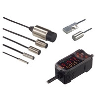
Sensor Heads
|
Model |
ZX-EDR5T |
ZX- |
ZX-ED02T/ |
ZX- |
ZX-EV04T |
ZX-EM02HT |
||
|
Measurement range |
0 to 0.5 mm |
0 to 1 mm |
0 to 2 mm |
0 to 7 mm |
0 to 4 mm |
0 to 2 mm |
||
|
Sensing object |
Magnetic metals (Measurement ranges and linearities are different for non-magnetic metals. Refer to Engineering Data on See Engineering Data (Typical).) |
|||||||
|
Standard reference object |
18 × 18 × 3 mm |
30 × 30 × |
60 × 60 × 3 mm |
45 × 45 × |
||||
|
Material: ferrous (S50C) |
||||||||
|
Resolution *1 |
1 μm |
|||||||
|
Linearity *2 |
± 0.5% F.S. |
± 1.0% F.S. *5 |
||||||
|
Linear output range |
Same as measurement range. |
|||||||
|
Temperature characteristic *3 |
0.15 % |
0.07% F.S./°C |
0.1% F.S./°C |
|||||
|
Ambient |
Operating *4 |
0 to 50°C |
-10 to 60°C (with no icing or condensation) |
-10 to 200°C |
||||
|
Storage *4 |
-20 to 70°C (with no icing or condensation) |
|||||||
|
Ambient humidity |
Operating and storage: 35% to 85% (with no condensation) |
|||||||
|
Insulation resistance |
50 MΩ min. (at 500 DC) |
|||||||
|
Dielectric strength |
1,000 VAC, 50/60 Hz for 1 min between charged parts and case |
|||||||
|
Vibration resistance (destruction) |
10 to 55 Hz with 1.5-mm double amplitude for 2 h each in X, Y, and Z directions |
|||||||
|
Shock resistance (destruction) |
500 m/s2, 3 times each in X, Y, and Z directions |
|||||||
|
Degree of protection |
IEC60529, |
IEC60529, IP67 |
IEC60529, |
|||||
|
Connection method |
Connector relay (standard cable length: 2 m) |
|||||||
|
Weight (packed state) |
Approx. |
Approx. 140 g |
Approx. |
Approx. |
Approx. 160 g |
|||
|
Materials |
Sensor |
Case |
Brass |
Stainless |
Brass |
Zinc (nickel- |
Brass |
|
|
Sensing |
Heat-resistant ABS |
PEEK |
||||||
|
Tightening |
--- |
Brass (nickel-plated) |
--- |
Brass |
||||
|
Toothed |
--- |
Iron (zinc-plated) |
--- |
Iron |
||||
|
Preamplifier |
PES |
|||||||
|
Accessories |
Amplifier Mounting Brackets (ZX-XBE1), Instruction Manual |
|||||||
1: Resolution: The resolution is the deviation (±3σ) in the linear output when connected to the ZX-EDA Amplifier Unit. The above values indicate the deviations observed 30 minutes after the power is turned ON. (The resolution is measured with OMRON's standard reference object at 1/2 of the measurement range with the ZX-EDA set for the maximum average count of 4,096 per period.) The resolution is given at the repeat accuracy for a stationary workpiece, and is not an indication of the distance accuracy. The resolution may be adversely affected under strong electromagnetic fields.
2: Linearity: The linearity is given as the error in an ideal straight line displacement output when measuring the standard reference object. The linearity and measurement values vary with the object being measured.
3: Temperature characteristic: The temperature characteristic is measured with OMRON's standard reference object at 1/2 of the measurement range.
4: The ambient temperature given is only for the sensor head. It is -10 to 60°C for the preamp.
5: The value given is for an ambient temperature of 25°C.
6: Do not use in moist environments because the case is not waterproof.
Amplifier Units
|
Model |
ZX-EDA11 |
ZX-EDA41 |
|
Measurement |
150 μs |
|
|
Possible average |
1, 2, 4, 8, 16, 32, 64, 128, 256, 512, 1,024, 2,048, or 4,096 |
|
|
Linear output *2 |
Current output: 4 to 20 mA/F.S., Max. load resistance: 300 Ω |
|
|
Judgement outputs |
NPN open-collector outputs, 30 VDC, 50 mA max. |
PNP open-collector outputs, 30 VDC, 50 mA max. |
|
Zero reset input, |
ON: Short-circuited with 0-V terminal or 1.5 V or less |
ON: Supply voltage short-circuited or supply voltage within 1.5 V |
|
Function |
- Number of display digit changes - Sample hold - Peak hold |
|
|
Indications |
Judgement indicators: High (orange), pass (green), low (yellow), 7-segment main digital display (red), 7-segment sub-digital display (yellow), power ON (green), zero reset (green), enable (green) |
|
|
Voltage influence |
0.5% F.S. of linear output value at ±20% of power supply voltage |
|
|
Power supply |
12 to 24 VDC ± 10%, Ripple (p-p): 10% max. |
|
|
Current |
140 mA max. with power supply voltage of 24 VDC (with Sensor connected) |
|
|
Ambient |
Operating and storage: 0 to 50°C (with no icing or condensation) |
|
|
Ambient humidity |
Operating and storage: 35% to 85% (with no condensation) |
|
|
Insulation |
20 MΩ min. (at 500 DC) |
|
|
Dielectric strength |
1,000 VAC, 50/60 Hz for 1 min |
|
|
Vibration resistance |
10 to 150 Hz with 0.7-mm double amplitude for 80 min each in X, Y, and Z directions |
|
|
Shock resistance |
300 m/s2, 3 times each in 6 directions (up, down, left, right, forward, backward) |
|
|
Connection method |
Prewired (standard cable length: 2 m) |
|
|
Weight |
Approx. 350 g |
|
|
Materials |
Case: PBT (polybutylene terephthalate), Cover: Polycarbonate |
|
|
Accessories |
Instruction Manual |
|
1: The response time for the first linear output or judgment output is calculated as follows (with fixed sensitivity): Measurement period × (Average count setting + 1). The response time for the second and later outputs is the measurement period specified in the table.
2: The output can be switched between a current output and voltage output using a switch on the bottom of the Amplifier Unit.
3: Setting is possible via the monitor focus function.
4: A Calculating Unit (ZX-CAL2) is required.