


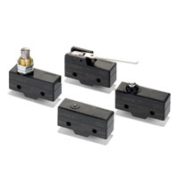
 Best-selling Basic Switch Boasting High Precision and Wide Variety
Ratings (Basic, Split-contact and Maintained contact Models)
Z-15 (Except Micro Load and Flexible Rod Models)
|
Item |
Non-inductive load (A) |
Inductive load (A) |
|
|||||||
|
Resistive load |
Lamp load |
Inductive load |
Motor load |
|
||||||
|
Contact gap |
Rated voltage |
NC |
NO |
NC |
NO |
NC |
NO |
NC |
NO |
|
|
G, H, H2, E |
125 VAC |
15 (10) * |
3 |
1.5 |
15 (10) * |
5 |
2.5 |
|
||
|
G |
8 VDC |
15 |
3 |
1.5 |
15 |
5 |
2.5 |
|||
|
H, H2 |
8 VDC |
15 |
3 |
1.5 |
15 |
5 |
2.5 |
|||
|
E |
8 VDC |
15 |
3 |
1.5 |
15 |
5 |
2.5 |
|||
* Figures in parentheses are for the Z-15HW52, Z-15HW78(-B) and Z-15H2(-B) models, the AC ratings of these models are 125 and 250 V only.
Z-15 (Flexible Rod Models)
|
Rated voltage |
Non-inductive load (A) |
Inductive load (A) |
|
||||||
|
Resistive load |
Lamp load Inductive load Motor load |
Lamp load Inductive load |
Motor load |
|
|||||
|
NC |
NO |
NC |
NO |
NC |
NO |
NC |
NO |
|
|
|
125 VAC |
15 |
2 |
1 |
7 |
2.5 |
2 |
|||
|
8 VDC |
15 |
2 |
1 |
7 |
3 |
1.5 |
|||
Z-10F
|
Item |
Non-inductive load (A) |
Inductive load (A) |
|
|||||||
|
Resistive load |
Lamp load |
Inductive load |
Motor load |
|
||||||
|
Contact gap |
Rated |
NC |
NO |
NC |
NO |
NC |
NO |
NC |
NO |
|
|
Series |
125 VAC |
10 |
4 |
2 |
6 |
5 |
2.5 |
|
||
|
30 VDC |
10 |
4 |
2 |
6 |
6 |
3 |
||||
|
Parallel |
125 VAC |
6 |
3 |
1.5 |
4 |
4 |
2 |
|
||
|
30 VDC |
6 |
4 |
2 |
4 |
6 |
3 |
||||
|
|
||||||||||
Z-01H
|
Rated voltage |
Resistive load (A) |
|
|
NC |
NO |
|
|
125 VAC |
0.1 |
|
|
8 VDC |
0.1 |
|
|
14 VDC |
0.1 |
|
|
30 VDC |
0.1 |
|
Note: 1. The above current ratings are the values of the steady-state current.
2. Inductive load has a power factor of 0.4 min. (AC) and a time constant of 7 ms max. (DC).
3. Lamp load has an inrush current of 10 times the steady-state current.
4. Motor load has an inrush current of 6 times the steady-state current.
5. The normally closed and normally open ratings of reverse hinge lever models are opposite to each other.
6. The AC ratings of molded terminals are 125 and 250 V only.
7. The ratings values apply under the following test conditions:
(1) Ambient temperature: 20±2°C
(2) Ambient humidity: 65±5%RH
(3) Operating frequency: 20 operations/min
Use the switch within the operating range.

|
Z-01H |
Z-15[], Z-10FY |
|
|
Minimum applicable load |
5 VDC 1 mA |
5 VDC 160 mA |
Certified Standard Ratings
Ask your OMRON representative for information on certified models.
UL/CSA (General ratings only)
|
Rated voltage |
Z-15 |
Z-10F |
Z-01H |
|
125 VAC |
15A 1/8HP |
6A 1/10HP |
0.1A |
|
250 VAC |
15A 1/4HP |
6A 1/8HP |
--- |
|
480 VAC |
15A |
6A |
--- |
|
30 VDC |
--- |
--- |
0.1A |
|
125 VDC |
0.5A |
0.6A |
--- |
|
250 VDC |
0.25A |
0.3A |
--- |
TÜV (EN61058-1)
|
Rated voltage |
Z-15H[] |
Z-15G[] |
Z-01H[] |
|
250 VAC |
15 A |
15 A |
--- |
|
125 VAC |
--- |
--- |
0.1 A |
|
30 VDC |
--- |
--- |
0.1 A |
CCC (GB/T14048.5)
|
Rated voltage |
Z-15H[] |
Z-15G[] |
Z-01H[] |
|
250 VAC |
15 A |
15 A |
--- |
|
125 VAC |
--- |
--- |
0.1 A |
|
30 VDC |
--- |
--- |
0.1 A |
Characteristics
|
Classification |
Z-15 (except |
Z-01H |
Z-15 |
Z-10F |
Z-15H2 |
|
|
Operating speed |
0.01 mm to 1 m/s *1 |
1 mm to 1 m/s |
0.1 mm to 1 m/s *1 |
0.01 mm to 1 m/s |
||
|
Operating |
Mechanical |
240 operations/min |
120 operations/min |
240 operations/min |
240 operations/min |
|
|
Electrical |
20 operations/min |
|||||
|
Insulation resistance |
100 MΩ min. (at 500 VDC) |
|||||
|
Contact resistance |
15 mΩ max. |
50 mΩ max. |
15 mΩ max. |
25 mΩ max. |
15 mΩ max. |
|
|
Dielectric strength |
Between contacts of |
Between contacts |
Between contacts |
Between contacts |
||
|
Between current-carrying metal parts and ground, and between each terminal and non-current-carrying metal parts 2,000 VAC, 50/60 Hz for 1 min |
||||||
|
Vibration |
Malfunction |
10 to 55 Hz, 1.5-mm |
10 to 20 Hz, 1.5- |
10 to 55 Hz, 1.5-mm double amplitude *5 |
||
|
Shock |
Destruction |
1,000 m/s2 max. |
||||
|
Malfunction |
300 m/s2 max. *2 *5 |
50 m/s2 max. *5 |
300 m/s2 max. |
100 m/s2 max. |
||
|
Durability |
Mechanical |
Contact gap G, H: |
1,000,000 |
500,000 |
20,000,000 |
|
|
Electrical |
Contact gap G, H: |
100,000 |
100,000 |
500,000 |
||
|
Degree of |
General- |
IP00 |
||||
|
Drip-proof |
Equivalent to IP62 (except terminals) |
|||||
|
Degree of protection |
Class I |
|||||
|
Proof tracking index |
175 |
|||||
|
Ambient |
General- |
- 25 °C to 80 °C (with no icing) |
||||
|
Drip-proof |
- 15 °C to 80 °C (with no icing) |
|||||
|
Ambient |
General- |
35% to 85%RH |
||||
|
Drip-proof |
35% to 95%RH |
|||||
|
Weight |
Approx. 22 to 58 g |
Approx. 42 to 48 g |
Approx. 34 to 61 g |
Approx. 22 g |
||
1. The values are for the plunger models. (For the lever models, the values are at the plunger section.) (Consult your OMRON representative for other models.)
2. The values are for the Z-15G pin plunger.
3. The values are for the Z-10FY-B.
4. The values are for the pin plunger. The durability for models other than the pin plunger is 10,000,000 min.
5. Malfunction: 1 ms max.
Contacts Specification
|
Item |
Classification |
Z-15 |
Z-01H |
Z-10F |
|
Contacts |
Shape |
Rivet |
Single crossbar |
Rivet |
|
Material |
Silver |
Gold alloy |
Silver |
|
|
Inrush current |
NC |
30 A max. |
0.1 A max. |
40 A max. |
|
NO |
15 A max. |
0.1 A max. |
20 A max. |