


Smart Sensor (2D Measurement Sensor)
ZG2
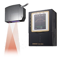 2D Laser Profile Measurement System. ZG2 debut! Achieving stable measurement through innovative technology.
Sensor Heads
|
Item |
ZG2-WDS8T |
ZG2-WDS22 |
ZG2-WDS70 |
ZG2-WDS3VT |
||||
|
Optical system |
Diffuse |
Regular |
Diffuse |
Regular |
Diffuse |
Regular |
Diffuse |
|
|
Meas- |
Height direction |
50 |
44 |
100 |
94 |
210 ± 48 mm |
22.3 |
10.6 |
|
Width direction *5 |
8 mm (typical) |
22 mm (typical) |
70 mm (typical) |
3 mm (typical) |
||||
|
Resolution |
Height direction |
1 μm |
2.5 μm |
6 μm |
0.25 μm |
|||
|
Width direction |
13 μm |
35 μm |
111 μm |
5 μm |
||||
|
Linearity (in the height |
± 0.1 %F.S. |
|||||||
|
Temperature characteristic |
0.03 %F.S./℃ |
0.02 %F.S./℃ |
0.08 %F.S./℃ |
|||||
|
Light |
Type |
Visible semiconductor laser |
||||||
|
Wavelength |
658 nm |
650 nm |
||||||
|
Output |
5 mW max. output, 1 mW max. exposure |
1 mW max |
||||||
|
Laser class |
Class 2M of EN60825-1/IEC60825-1 |
Class 2 of |
||||||
|
Beam shape (at measurement |
30 μm × 24 mm |
60 μm × 45 mm |
120 μm × |
25 μm × 4 mm |
||||
|
LED |
STANDBY: Lights when laser irradiation preparation is complete (indication color: |
|||||||
|
LD_ON: Lights when the laser is irradiating (indication color: green) |
||||||||
|
Measurement object |
Surface of non-transparent/transparent |
Surface of non- |
Surface of non- |
|||||
|
Environ- |
Ambient light |
Illumination on the photo-receiving face 7,000 lx max.: Incandescent lamp |
||||||
|
Ambient |
Operating: 0 to 50℃, Storage: -15 to 60℃ (with no icing or condensation) |
|||||||
|
Ambient humidity |
Operating and storage: 35 to 85 % (with no condensation) |
|||||||
|
Degree of |
IP66(IEC60529) |
IP67(IEC60529) |
||||||
|
Vibration |
10 to 150 Hz with 0.35 mm single amplitude for 80 min each in X, Y, and Z directions |
|||||||
|
Shock resistance |
150 m/s2, 3 times each in 6 directions (up/down, right/left, forward/backward) |
|||||||
|
Materials |
Case: Aluminum diecast, Front cover: Glass, Cable insulation: Heat-resistive |
|||||||
|
Cable length |
0.5 m, 2 m (flexible cable) |
|||||||
|
Minimum bending radius |
68 mm |
|||||||
|
Weight |
Approx. 500 g |
Approx. 500 g |
Approx. 650 g |
Approx. 300 g |
||||
|
Accessories |
Laser labels (English labels), Ferrite core (2), Instruction manual |
|||||||
1. Obtained by setting an OMRON standard measurement object at the measurement center distance and determining the average height of the beam line. The conditions are given in the table below. However, satisfactory resolution cannot e attained in strong electromagnetic fields.
The minimum resolution of the ZG2-WDS8T/WDS3VT is 0.25 μm, even when the average number of operations is increased. Resolution does not go any lower.
|
Model |
CCD |
Average No. |
Measurement object |
|
|
Regular reflective |
Diffuse reflective |
|||
|
ZG2-WDS8T/ |
High- |
64 |
OMRON standard white alumina ceramic obje |
|
|
ZG2-WDS3VT |
OMRON standard mirrored object |
OMRON standard diffuse reflective |
||
2. The tolerance for and ideal straight line obtained by determining the average height of and OMRON standard measurement object for the beam line.The CCD high-resolution mode is used. Linearity varies depending on the measurement object.
|
Model |
CCD |
Average No. |
Measurement object |
|
|
Regular reflective |
Diffuse reflective |
|||
|
ZG2-WDS8T/ |
High- |
1 |
OMRON standard white alumina ceramic object |
|
|
ZG2-WDS3VT |
OMRON standard mirrored object |
OMRON standard diffuse reflective |
||
3. A value attained by using an aluminum jig to secure the distance between the Sensor Head and the measurement object. The CCD standard mode is used.
4. Defined as 1/e2 (13.5%) of the center light intensity.This may be influenced when light leakage also exists outside the defined area and the reflectivity of the light around the measurement object is higher than that of the measurement object.
5. A typical value of the measurement range (width direction) near the measurement center distance. This is not a guaranteed value.
6. Protection structure of connector area is IP40.
Sensor Controllers
|
Item |
ZG2-WDC11/WDC11A |
ZG2-WDC41/WDC41A |
||
|
Input/output type |
NPN |
PNP |
||
|
No. of connectable Sensor Heads |
1 per Controller |
|||
|
No. of connectable Controllers |
2 |
|||
|
Measurement cycle * |
16 ms (high-precision mode), 8 ms (standard mode), 5 ms (high- |
|||
|
Min. display unit |
10 nm |
|||
|
Display range |
-999.99999 to 999.99999 |
|||
|
Display |
LCD monitor |
2.2-inch TFT color LCD (557 x 234 pixels) |
||
|
LEDs |
Judgment indicators for each task (indication color: orange): T1, |
|||
|
External |
Input/ |
Analog outputs |
Select voltage or current (using the sliding switch on the bottom |
|
|
Judgment output |
NPN open collector |
PNP open collector |
||
|
Trigger auxiliary output |
||||
|
Laser stop input |
ON: O V short or 1.5 V max. |
ON: Power supply voltage |
||
|
Zero reset input (ZERO) |
||||
|
Measurement trigger |
||||
|
Bank switching input |
||||
|
Serial I/O |
USB2.0 |
1 port, full speed (12 Mbps), MINI-B |
||
|
RS-232C |
1 port, 115,200 bps max. |
|||
|
Parallel |
Output |
18 - terminal |
||
|
Main functions |
No. of setting banks |
16 |
||
|
Sensitivity adjustment |
Multi, High-speed multi, Auto, Fixed |
|||
|
Measurement items |
Height, 2-point Step, 3-point Step, Edge position, Edge width, |
|||
|
Auxiliary functions |
Filter, Laser power adjustment, Position correction (height, |
|||
|
Profiles saved |
16 profiles (1 profile per bank) |
|||
|
Trigger modes |
External trigger/continuous |
|||
|
Ratings |
Power supply voltage |
21.6 to 26.4 VDC (including ripple current) |
||
|
Current consumption |
0.8 A max. (per sensor head) |
|||
|
Insulation resistance |
20 MΩ at 250 V between lead wires and Controller case |
|||
|
Dielectric strength |
1,000 VAC, 50/60 Hz for 1 min between lead wires and Controller |
|||
|
Environmental |
Ambient temperature |
Operating: 0 to 50℃, Storage: -15 to 60℃ (with no icing or |
||
|
Ambient humidity |
Operating and storage: 35 to 85 % (with no condensation) |
|||
|
Degree of protection |
IP20 (IEC60529) |
|||
|
Vibration resistance |
Vibration frequency: 10 to 150 Hz, single amplitude: 0.35 mm, |
|||
|
Shock resistance |
150 m/s2, 3 times each in 6 directions (up/down, right/left, |
|||
|
Material |
Case: Polycarbonate (PC), |
|||
|
Cable length |
2 m |
|||
|
Minimum bending radius |
57 mm |
|||
|
Weight |
Approx. 300 g (including cable)(Packed state: Approx. 450 g) |
|||
|
Accessories |
ZG2-WDC_1: Large Ferrite Core (1 piece), Insure Lock (1 piece), |
|||
1. The measurement cycles stated here are values for FIXED/AUTO sensitivity modes. The measurement cycle increases when the MULTI sensitivity/high-speed MULTI sensitivity mode is selected and according to other settings. When the high power mode is set to ON, the shortest measurement cycle becomes 95 ms regardless of the CCD mode setting. Also, when gang-mounting Controllers and Data Storage Units, the measurement cycle increases approximately 22 ms. The actual measurement cycle can be checked by the ECO monitor in RUN mode.
2. SmartMonitor ZG2
System Requirements
OS: Windows 10 (32-bit/64-bit version)
Windows 7 (32-bit/64-bit version)
Windows XP (Service Pack3 or higher, 32-bit version)
CPU: Intel Pentium III 1 GHz or faster (2 GHz min. recommended.)
Memory: 1 GB min.
Display screen: 1,024 × 768 dots min., 16 million colors min.
- Window is registered trademarks of Microsoft Corporation in the USA and other countries.
- Other company names and product names in this document are the trademarks or registered
trademarks or their respective companies.
Data Storage Unit
|
Item |
ZG2-DSU11 |
ZG2-DSU41 |
||
|
Input/output type |
NPN |
PNP |
||
|
No. of connectable Controllers |
2 *1 |
|||
|
Connectable Controllers |
ZG2-WDC11/WDC41 |
|||
|
External |
Input/ |
Inputting |
ON: O V short or 1.5 V max. |
ON: Power supply voltage short or power |
|
Judgment output |
NPN open collector |
PNP open collector |
||
|
Serial |
USB2.0 |
1 port, full speed (12 Mbps), MINI-B |
||
|
RS-232C |
1 port, 115,200 bps max. |
|||
|
Functions |
No. of |
Memory of the |
Profiles saved: 5,120 profiles |
|
|
Memory card |
Profiles saved: 35,328 profiles max. (256 profiles x 138 files) |
|||
|
Logging trigger functions |
External triggers, data triggers (self-triggers), and time triggers |
|||
|
External banks functions |
4096 |
|||
|
Other functions |
Alarm output functions |
|||
|
Ratings |
Power supply voltage |
21.6 to 26.4 VDC (including ripple current) |
||
|
Current consumption |
0.5 A max. |
|||
|
Environ- |
Ambient temperature |
Operating: 0 to 50℃, Storage: 0 to 60℃ (with no icing or condensation) |
||
|
Ambient humidity |
Operating and storage: 35 to 85% (with no condensation) |
|||
|
Degree of protection |
IP20 (IEC60529) |
|||
|
Material |
Case: Polycarbonate (PC) |
|||
|
Cable length |
2 m |
|||
|
Minimum bending radius |
52 mm |
|||
|
Weight |
Approx. 280 g |
|||
|
Accessories |
Ferrite Core (1 piece), Instruction Manual |
|||
1. The controller link unit is necessary for linking.
2. Data is saved in the memory of the main unit during logging. The data is automatically saved in a memory card after logging is completed.The maximum number of logging differs according to set conditions.
3. Measurement values for 65,000 measurements can be saved even when two sensor controllers are connected and each performs eight tasks.
4. The value is the maximum number achieved in the following conditions. One sensor controller performs one measurement task. Either profiles or measurement values are logged.