


Confocal Fiber Displacement Sensor Sensor Head
ZW-SQ Series
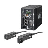 Ultra-compact and Ultra-lightweight. Stable Measurements for Any Material
Sensor Head
|
Item |
ZW- |
ZW- |
ZW- |
ZW- |
ZW- |
ZW- |
ZW- |
|
|
Sensor Controller |
ZW-5000[] |
|||||||
|
Sensor Head |
Square straight type |
Square Right-angle type |
||||||
|
Measuring center |
7 mm |
20 mm |
30 mm |
40 mm |
7 mm |
20 mm |
40 mm |
|
|
Measuring range |
±0.3 mm |
±1 mm |
±3 mm |
±6 mm |
±0.3 mm |
±1 mm |
±6 mm |
|
|
Static resolution *1 |
0.25 μm |
|||||||
|
Linearity *2 |
±0.8 μm |
±1.2 μm |
±4.5 μm |
±7.0 μm |
±1.1 μm |
±1.6 μm |
±9.3 μm |
|
|
Spot |
Near |
20 μm dia. |
45 μm dia. |
70 μm dia. |
90 μm dia. |
20 μm dia. |
45 μm dia. |
90 μm dia. |
|
Center |
18 μm dia. |
40 μm dia. |
60 μm dia. |
80 μm dia |
18 μm dia. |
40 μm dia. |
80 μm dia |
|
|
Far |
20 μm dia. |
45 μm dia. |
70 μm dia. |
90 μm dia |
20 μm dia. |
45 μm dia. |
90 μm dia |
|
|
Measuring cycle *4 |
80 μs to 1600 μs |
|||||||
|
Operating ambient |
Illumination on object surface 10,000 lx or less: incandescent light |
|||||||
|
Ambient temperature |
Operating: 0 to 50°C, Storage: -15 to 60°C (with no icing or condensation) |
|||||||
|
Ambient humidity |
Operating and storage: 35% to 85%RH (with no condensation) |
|||||||
|
Degree of protection |
IP40 (IEC60529) |
|||||||
|
Vibration resistance |
10 to 150 Hz, 0.35 mm single amplitude, 80 min each in X, Y, and Z directions |
|||||||
|
Shock resistance |
150 m/s2 3 times each in six directions (up/down, left/right, forward/backward) |
|||||||
|
Temperature |
0.6 μm/ °C |
1.5 μm/ °C |
2.8 μm/ °C |
4.8 μm/ °C |
0.6 μm/ °C |
1.5 μm/ °C |
4.8 μm/ °C |
|
|
LED Safety |
Risk Group 1 (IEC62471) |
|||||||
|
Materials |
Case: aluminum die-cast |
|||||||
|
Fiber cable length |
0.3 m, 2 m (Flex-resistant cable) |
|||||||
|
Fiber cable minimum |
20 mm |
|||||||
|
Insulation resistance |
Between case and all terminals: 20 MΩ (by 250 V megger) |
|||||||
|
Dielectric strength |
Between case and all terminals: 1,000 VAC, 50/60 Hz, 1 min |
|||||||
|
Weight |
Fiber cable length 0.3 m Approx. 100g |
Fiber cable length 0.3 m Approx. 125g |
||||||
|
Accessories included |
Calibration ROM fixing screws (M2 × 5mm) ×1, Fiber protection cap × 1, Strap × 1, |
|||||||
1. Capacity value when OMRON standard mirror surface target is measured at the measurement center distance as the average of 16,384 times
The value when the sensor controller ZW-5000T is connected
2. Material setting for the OMRON standard mirror surface target: Error from an ideal straight line when measuring on mirror surface
3. Capacity value defined by 1/e2 (13.5%) of the peak optical intensity of the measurement wavelength.
4. When an extension fiber cable of 5 m or longer is connected, the setting rage of the measurement cycle (exposure time) changes. For details, refer to Setting Measurement Cycle in the ZW-8000/7000/5000 User's Manual (Cat. No. Z362).
5. Capacity value of temperature characteristic at the measurement center distance when fastened with an aluminum jig between the Sensor Head and the target and the Sensor Head and the Sensor Controller are set in the same temperature environment.
Sensor Controller
|
Item |
ZW-5000T |
|||
|
Input/output type |
NPN/PNP dual type |
|||
|
Number of connected sensor heads |
1 |
|||
|
Sensor head compatibility |
ZW-SQ50[][]/SQR50[][] |
|||
|
LED Safety |
Risk Group 1 (IEC62471) |
|||
|
Segment |
Main display |
11-segment white display, 6 digits |
||
|
Sub-display |
11-segment green display, 6 digits |
|||
|
Display |
Status indicators |
HIGH (orange), PASS (green), LOW (orange), STABILITY (green), |
||
|
EtherCAT indicator |
ECAT RUN (green), L/A IN (Link/Activity IN) (green), L/A OUT |
|||
|
External |
Ethernet |
100BASE-TX/10BASE-T, Non-procedure (TCP/UDP), EtherNet/IP |
||
|
EtherCAT |
EtherCAT exclusive protocol 100BASE-TX |
|||
|
RS-232C |
Max. 115,200 bps |
|||
|
Analog |
Analog voltage output |
-10 V to +10 V, output impedance: 100 Ω |
||
|
Analog current output |
4 mA to 20 mA, max. load resistance: 300 Ω |
|||
|
32-pole |
Judgment output |
Transistor output system |
||
|
Busy output (BUSY) |
||||
|
Alarm output (ALARM) |
||||
|
Enable output |
||||
|
Sync flag output |
||||
|
Trigger busy output |
||||
|
Logging state output |
||||
|
Logging error output |
||||
|
Stability output |
||||
|
Task state output |
||||
|
LIGHT OFF input |
DC input system |
|||
|
Zero reset input |
||||
|
Timing input (TIMING) |
||||
|
Reset input (RESET) |
||||
|
Sync input (SYNC) |
||||
|
Trigger input (TRIG) |
||||
|
Logging input |
||||
|
Bank |
Currently |
Transistor output system |
||
|
Bank Selection |
DC input system |
|||
|
Main |
Exposure time |
Automatic/Fixed |
||
|
Measuring cycle *1 |
80 μs to 1600 μs |
|||
|
Material setting |
Standard/Mirror/Rough surfaces |
|||
|
Measurement item |
Height/Thickness of transparent object/Calculation |
|||
|
Filtering |
Median/Average/Differentiation/High pass/Low pass/Band pass |
|||
|
Output |
Scaling/Different holds/Zero reset/Logging for a measured value/ |
|||
|
Display |
Measured value/Threshold value/Analog output voltage or current |
|||
|
Number of configurable banks |
Max. 8 banks (NORMAL mode) |
|||
|
Task process |
Multi-task (up to 4 tasks per bank) |
|||
|
System |
Save/Initialization/Display measured information/Communication |
|||
|
Rating |
Power supply voltage |
21.6 to 26.4 VDC (including ripple) |
||
|
Current consumption |
800 mA max. |
|||
|
Insulation resistance |
Across all lead wires and FG terminal: 20 MΩ (by 250 VDC) |
|||
|
Dielectric strength |
Between all lead wires and FG terminal: 500 VAC, 50/60 Hz, |
|||
|
Environ- |
Degree of protection |
IP20 (IEC60529) |
||
|
Vibration resistance (destructive) |
10 to 55 Hz (half amplitude 0.35 mm), 50 mins in each of X/Y/Z |
|||
|
Shock resistance (destructive) |
150 m/s2, 6 direction, 3 times each (up/down, left/right, forward/ |
|||
|
Ambient temperature range |
Operation: 0 to 40°C, Storage: -15 to +60°C (No freezing and |
|||
|
Ambient humidity range |
Operation/storage: 35 to 85%RH (No condensation) |
|||
|
Grounding |
D-type grounding (grounding resistance of 100 Ω or less) |
|||
|
Material |
Chassis: PC |
|||
|
Weight |
Approx. 900g (main unit only), Approx. 150 g (Parallel cable) |
|||
|
Accessories |
Parallel cable × 1 (ZW-XCP2E) |
|||
Note: The Export Trade Control Order compatible Sensor Controller (ZW-5000T) is available.
When using this Sensor Controller, the minimum resolution is 0.25 μm regardless of the connected Sensor Head and setting conditions.
1. When an extension fiber cable of 5 m or longer is connected, the setting rage of the measurement cycle (exposure time) changes. For details, refer to Setting Measurement Cycle in the ZW-8000/7000/5000 User's Manual (Cat. No. Z362).
EtherCAT Communications Specifications
|
Item |
Specification |
|
Communications standard |
IEC61158 Type12 |
|
Physical layer |
100BASE-TX(IEEE802.3) |
|
Connectors |
RJ45 × 2 |
|
Communications media |
Category 5 or higher (cable with double, aluminum tape and braided shielding) is |
|
Communications distance |
Distance between nodes: 100 m max. |
|
Process data |
Variable PDO mapping |
|
Mailbox (CoE) |
Emergency messages, SDO requests, SDO responses, and SDO information |
|
Distributed clock |
Synchronization in DC mode. |
|
LED display |
L/A IN (Link/Activity IN) × 1, AL/A OUT (Link/Activity OUT) × 1, AECAT RUN × 1, |
Automation Software Sysmac Studio
|
Item |
Operating environment *3 |
|
Operating system (OS) |
Windows 7 SP1 (32-bit/64-bit version)/Windows 8.1 (32-bit/64-bit version)/ |
|
CPU |
Windows computers with Intel® Celeron® processor 540 (1.8 GHz) or faster CPU. |
|
Main memory |
2 GB min. |
|
Hard disk |
Minimum 4.6 GB of Hard disk space is required to install. *2 |
|
Display |
XGA 1024 × 768, 16 million colors. |
|
Disk drive |
DVD-ROM drive |
|
Communications ports |
USB port corresponded to USB 2.0, or Ethernet port *4 |
|
Supported languages |
Japanese, English, German, French, Italian, Spanish, simplified Chinese, traditional Chinese, |
1. Note about Sysmac Studio compatible operating systems: The required system and hard disk capacity differs according to the system environment.
2. Separate logging memory is required to use the file logging function.
3. Describes System Requirements and notes of Sysmac Studio Measurement Sensor Edition.
For detail of System Requirements and notes of Sysmac Studio Measurement Sensor Edition, refer to Sysmac Studio Version 1 Operation Manual.
4. For information on how to connect a personal computer with the sensor controller or other hardware and information on required cables, refer to manuals for each hardware.
Version Information
Sensor Head/Cable, Sensor Controller, and Sysmac Studio
The applicable version of the Sensor Controller varies depending on the Sensor Head or Cable. The versions are listed below.
Use the latest version of Sysmac Studio Standard Edition/Measurement Sensor Edition.
|
Sensor head/Cable |
ZW |
Version of |
Corresponding version of Sysmac Studio |
|
|
Type |
Model |
|||
|
Square straight |
ZW-SQ50[][] []M |
ZW- |
Version 2.110 or |
Version 1.18 or higher |
|
Square Right- |
ZW-SQR50[][] []M |
|||
|
Extension Fiber |
ZW-XF50[][]R |
Version 2.100 or |
||
Note: Refer to the Firmware Update in the ZW-8000/7000/5000 User's Manual (Cat. No. Z362) for how to update the Sensor Controller.