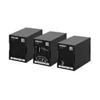
Floatless Level Switch (Compact, Plug-in Type)
61F-LS
 Consolidates the Specifications through Free Power Supply, thus Allowing Use in High Temperature Environments with Temperatures of Up to 70°C* * Excluding the DC power supply type.
Specifications
Ratings
|
61F-LS-CP[]-N |
61F-LS-CP[]-S/-A |
61F-LS-CP11-B |
|
|
Controlling materials |
• For control of ordinary |
• For control of liquids with |
• When using DC power |
|
Supply |
100 - 240 VAC 50/60 Hz |
100 - 240 VAC 50/60 Hz |
24 VDC |
|
Operating voltage |
85% to 110% of rated |
85% to 110% of rated |
85% to 110% of rated |
|
Operating frequency |
±5 Hz of the rated frequency |
±5 Hz of the rated frequency |
±5 Hz of the rated frequency |
|
Power consumption |
Approx. 3.2 VA max. |
Approx. 3.2 VA max. |
Approx. 1 W max. |
|
Contact ratings |
5 A at 250 VAC |
5 A at 250 VAC |
Transistor output |
|
Ambient temperature |
-10 to +70°C |
-10 to +70°C |
-10 to +55°C |
|
Ambient humidity |
25 to 90% RH |
25 to 90% RH |
25 to 85% RH |
|
Ambient storage |
-10 to +70°C |
-10 to +70°C |
-10 to +55°C |
|
Ambient storage |
25 to 90% RH |
25 to 90% RH |
25 to 85% RH |
|
Weight |
Approx. 100 g |
Approx. 100 g |
Approx. 100 g |
|
Accessories |
PFC-N8 |
||
|
Wiring distance *1 |
4 km or less |
Ultra low-sensitivity, |
100 m or less |
1. Reference values. The wiring distance indicates the values when completely-insulated, 3-core 0.75 mm2, 600-V VCT cables are used.
Characteristics
|
61F-LS-CP[]-N |
61F-LS-CP[]-S/-A |
61F-LS-CP11-B |
|
|
Operation resistance |
4 kΩ or more |
*2 |
Variable (0 to 100 kΩ) |
|
Operation resistance |
--- |
--- |
Scale 0: 0 to 10 kΩ *3 |
|
Release resistance |
15 kΩ or less |
*2 |
200% max. of the |
|
Interelectrode voltage |
5 VAC |
5 VAC |
5 VAC |
|
Response time |
Operate: 80 ms max. |
*2 |
Operate: 1.5 s max. |
|
Startup lock time |
3 s after turning on the power supply (The LED blinks during the startup lock time) |
||
|
Insulation resistance *4 |
100 MΩ min. (at 500 VDC) |
||
|
Dielectric strength *4 |
2000 VAC, 50/60 Hz for 1 min. |
||
|
Life expectancy |
Electrical: |
Electrical: |
Relay specification only |
|
Switching between |
--- |
--- |
Terminals 7 and 8 open: |
|
Approved standards |
UL61010-1, CAN/CSA C22.2 No.61010-1 |
||
2. Refer to Dip Switch Settings.
3. The Detector may not operate around the setting value of “0.” Adjust the sensitivity depending on the actual application.
4. The insulation resistance and dielectric strength indicate values between power terminals and Electrode terminals, between power terminals and contact terminals, and between Electrode terminals and contact terminals. Refer to Safety Precautions on Catalog.
Dip Switch Settings (61F-LS-CP[]-S/-A only)
|
Symbol |
Item |
Specification |
Notes |
Factory default |
|
|
(A) |
Response |
5S |
|||
|
INSTANT (Instantaneous) |
✓ |
||||
|
(B) |
Operation |
Operation |
Release |
||
|
0.5 kΩ or more |
2.5 kΩ or less |
Ultra low-sensitivity |
|||
|
1.3 kΩ or more |
4 kΩ or less |
Low-sensitivity |
|||
|
4 kΩ or more |
15 kΩ or less |
General-purpose |
✓ |
||
|
70 kΩ or more |
300 kΩ or less |
High-sensitivity |
|||
|
200 kΩ or more |
500 kΩ or less |
Ultra high-sensitivity |
|||

1. N/A indicates that the switch operates whether it is set ON or OFF.
2. “0.5, 1.3, 4, 70, 200” indicate the values of operation resistance.


