


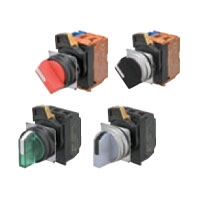
 22-mm dia. Knob-type Selector Switches. Control panel miniaturization through a more compact design and modified wiring direction. Addition of Push-In Plus terminal blocks for easy wiring.
Certified Safety Standard Ratings
UL 508 (File No. E76675), CSA C22.2 No.14
6 A 240 VAC, 10 A 120 VAC
TÜV (EN60947-5-1)
AC-15 3 A 240 VAC
DC-13 4 A 24 VDC
CCC (GB/T14048.5)
AC-15 3 A 240 VAC
DC-13 4 A 24 VDC
Application Standards
UL1059 and UL486E (Push-In Plus terminal block type)
Ratings
Contacts (Standard Load)
|
Rated insulation voltage |
600 V |
|||||
|
Rated carry current |
10 A |
|||||
|
Rated voltage |
24 V |
120 V |
240 V |
380 V |
440 V |
|
|
AC at 50/60 Hz |
Resistive load (AC-12) |
10 A |
10 A |
6 A |
2 A |
2 A |
|
Inductive load (AC-15) |
10 A |
6 A |
3 A |
1.9 A |
1.6 A |
|
|
DC |
Resistive load (DC-12) |
8 A |
2.2 A |
1.1 A |
--- |
--- |
|
Inductive load (DC-13) |
4 A |
1.1 A |
0.55 A |
--- |
--- |
|
Note: 1. The above ratings were obtained by conducting tests under the following conditions.
(1) Ambient temperature: 20 ±2°C
(2) Ambient humidity: 65% ±5% RH
(3) Operating frequency: 30 operations/minute
2. Minimum applicable load: 10 mA at 5 VDC.
LED Lamps
|
Rated voltage |
Applied voltage |
Rated current |
|
6 VAC/DC |
6 VAC/DC ±10% |
Approx. 11 mA (red, orange, yellow, or blue) |
|
12 VAC/DC |
12 VAC/DC ±10% |
Approx. 12 mA (red, orange, yellow, or blue) |
|
24 VAC/DC |
24 VAC/DC ±10% |
Approx. 12 mA (red, orange, yellow, or blue) |
|
100 VAC |
100 VAC ±10% |
Approx. 12 mA (red, orange, yellow, or blue) |
|
110 VAC |
110 VAC ±10% |
|
|
120 VAC |
100 to 130 VAC |
|
|
200 VAC |
200 VAC ±10% |
Approx. 12 mA (red, orange, yellow, or blue) |
|
220 VAC |
220 VAC ±10% |
|
|
230 VAC |
230 VAC ±10% |
|
|
240 VAC |
220 to 250 VAC |
Characteristics
|
Type |
Selector Switches |
||
|
Item |
Non-lighted models |
Lighted models |
|
|
Allowable |
Mechanical |
30 operations/minute max. |
|
|
Electrical |
30 operations/minute max. |
||
|
Insulation resistance |
100 MΩ min. (at 500 VDC) |
Not available for lighting units |
|
|
Contact resistance |
100 mΩ max. (initial value) |
||
|
Dielectric |
Between terminals of |
2,500 VAC at 50/60 Hz for 1 min. |
Not available for lighting units |
|
Between each terminal |
2,500 VAC at 50/60 Hz for 1 min. (initial value) |
||
|
Vibration |
Malfunction |
10 to 55 Hz, 1.5-mm double amplitude (malfunction within 1 ms) |
|
|
Shock |
Malfunction |
1,000 m/s2 max. (malfunction within 1 ms) |
|
|
Durability |
Mechanical |
500,000 operations min. (Switches with 3 positions: 300,000 operations min.) |
|
|
Electrical |
500,000 operations min. (Switches with 3 positions: 300,000 operations min.) |
||
|
Ambient operating temperature *1 |
-25 to 70°C |
-25 to 55°C |
|
|
Ambient operating humidity |
35% to 85% RH |
||
|
Ambient storage temperature *1 |
-40 to 80°C |
||
|
Degree of protection *2 |
Conforming to IP66, NEMA 4X, NEMA 13 |
||
|
Electric shock protection class |
Class II |
||
|
PTI (tracking characteristic) |
175 |
||
|
Degree of contamination (application |
3 (EN 60947-5-1) |
||
|
Weight |
Approx. 50 g (for 1NC/1NO) |
Approx. 60 g (for 1NC/1NO) |
|
*1. With no icing or condensation.
*2. Degree of protection from the front of the panel.
Operating Characteristics (for SPST-NO/SPST-NC)
|
Type |
Selector Switches |
|
|
Item |
Manual reset |
Automatic reset |
|
Total travel force (torque) (maximum TTF) |
0.6 Nm |
0.6 Nm |
|
Total travel (TT) |
2 positions: Approx. 90°, 3 positions: Approx. 45° |
|
|
Resetting force (torque) (RF) |
0.5 N·m max. |
--- |
Examples of Linked Contact Blocks (Screw terminal block type)

|
Selector Switches |
||||
|
2 positions |
3 positions |
|||
|
Lighted |
Non-lighted |
Lighted |
Non-lighted |
|
|
Linking example |
|
|
|
|


* If you use three Contact Blocks in stage 1, you can add one more Contact Block in the middle of stage 2.
Note: If you increase the number of Contact Blocks, evaluate the Switch under actual working conditions before permanent installation and use the Switch within a number of switching operations that will not adversely affect the Switch's performance.