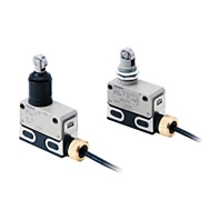
Oil-resistant Limit Switch
D4ER-[]N
 Even Better Oil Resistance Than D4E-N Switches
Approved Standards
|
Agency |
Standard |
File No. |
Approved models |
|
TÜV Rheinland |
EN 60947-5-1 |
R9551015, J9951016 |
Ask your OMRON representative |
|
CCC |
- |
- |
|
|
UL |
- |
- |
Ratings
|
Rated |
Standard load |
Micro load |
|||||||||||
|
Non-inductive load (A) |
Inductive load (A) |
Non-inductive load (A) |
|||||||||||
|
Resistive load |
Lamp load |
Inductive load |
Motor load |
Resistive load |
|||||||||
|
NC |
NO |
NC |
NO |
NC |
NO |
NC |
NO |
NC |
NO |
||||
|
8 VDC |
1 |
- |
1 |
- |
0.1 |
||||||||
|
Minimum |
Standard load |
Micro load |
|||||||||||
|
160 mA at 5 VDC |
1 mA at 5 VDC |
||||||||||||
|
Inrush current |
NC |
10 A max. |
|
NO |
10 A max. |
Note: 1. The above current ratings are for a standard current.
2. Inductive loads have a power factor of 0.4 min. (AC) and a time constant of 7 ms max. (DC).
3. Lamp load has an inrush current of 10 times the steady-state current.
4. Motor load has an inrush current of 6 times the steady-state current.
Approved Standard Ratings
TÜV (EN 60947-5-1)

|
Model |
Applicable category |
Thermal current |
||
|
I |
II |
III |
||
|
1 |
[] |
21/22 |
DC-12 1 A/30 VDC |
1A |
Note: 1. []:Actuator variation of item II
2. DC-12 1 A/30 VDC means as follows:
Applicable category: DC-12
Rated operating current (Ie): 1 A
Rated operating voltage (Ue): 30 VDC
Characteristics (Standard Load Model and Micro Load Model)
|
Degree of protection |
IP67 (IEC 60529) and IP67G (JIS C 0920 Annex 1) *1 |
|
|
Durability |
Mechanical |
4,000,000 operations min. |
|
Electrical |
500,000 operations min. |
|
|
Operating speed |
0.1 mm/sec to 0.5 m/sec |
|
|
Operating frequency |
Mechanical: 120 operations/min |
|
|
Insulation resistance |
100 MΩ min. (at 500 VDC) *3 |
|
|
Contact resistance |
Standard load: D4ER-1[][][]N[]: 15 mΩ max. |
|
|
Dielectric |
Between terminals of |
1,000 VAC, 50/60 Hz for 1 min |
|
Between each |
1,500 VAC, 50/60 Hz for 1 min/Uimp at 2.5 kV |
|
|
Rated insulation voltage (Ui) |
250 V |
|
|
Pollution degree |
3 (EN 60947-5-1) |
|
|
Short-circuit protective device |
10 A fuse (type gG or type gI, IEC 60269 approved) |
|
|
Conditional short-circuit current |
100 A (EN 60947-5-1) |
|
|
Conventional enclosed |
5 A (EN 60947-5-1) |
|
|
Protection against electric shock |
Class II (grounding not required with double insulation) |
|
|
Vibration |
Malfunction |
10 to 55 Hz, 1.5-mm double amplitude |
|
Shock |
Destruction |
1,000 m/s2 max. (IEC 68-2-27) |
|
Malfunction |
300 m/s2 max. (IEC 68-2-27) |
|
|
Ambient operating |
5°C to 70°C (with no icing or condensation) |
|
|
Ambient operating humidity |
35% to 95%RH (with no condensation) |
|
|
Weight |
(in case of roller plunger) |
|
Note: 1. The following values are initial values.
2. The following ratings may vary depending on the model. Contact your OMRON representative for further details.
*1. The IP67G is the degree of protection which is defined according to the JIS (Japanese Industrial Standards).
The IP67 indicates the same level of protection as defined by the IEC, and the G indicates that a device has resistance to oil.
*2. The Oil-resistant Component Evaluation Standards are OMRON’s own durability evaluation standards.
The Pre-wired Connector type meets the degree of protection when it is correctly connected with an XS5[]R Oil-resistant Connector.
The degree of protection is not satisfied with the part where there is no XS5FR Oil-resistant Connector connected and cable wires are uncovered. And as for the Cable type, the degree of protection is not satisfied with the part where cable wires are uncovered.
*3. This value represents the condition when the Switch is shipped from the factory.


