


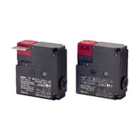
 Best-selling Guard Lock Safety-door Switch Available in Several Compact, Multi-contact Models
Standards and EC Directives
Conforms to the following EC Directives:
• Machinery Directive
• Low Voltage Directive
• EN ISO 14119
• EN60947-5-1
• Low Voltage Directive
• EN ISO 14119
• EN60947-5-1
Certified Standards
Standard type
Certification body | Standard | File No. |
TÜV SÜD | EN60947-5-1 (certified direct opening) | Consult your OMRON representative for details. |
UL *1 | UL508, CSA C22.2 No.14 | E76675 |
CQC (CCC) | GB/T 14048.5 | Consult your OMRON representative for details. |
KOSHA *2 | EN60947-5-1 | Consult your OMRON representative for details. |
*1. Certification for CSA C22.2 No. 14 is authorized by the UL mark.
*2. Only certain models have been certified.
*2. Only certain models have been certified.
Metallic release key type
Certification body | Standard | File No. |
TÜV SÜD | EN60947-5-1 (certified direct opening) | Consult your OMRON representative for details. |
KOSHA | EN60947-5-1 | Consult your OMRON representative for details. |
Certified Standard Ratings
TÜV (EN60947-5-1), CCC (GB/T 14048.5)
Utilization category | AC-15 | DC-13 |
Rated operating current (Ie) | 3 A | 0.27 A |
Rated operating voltage (Ue) | 240 V | 250 V |
Note: Use a 10 A fuse type gI or gG that conforms to IEC60269 as a short-circuit protection device. This fuse is not built
into the Switch.
into the Switch.
UL/CSA (UL508, CSA C22.2 No. 14)
A300
Rated voltage | Carry current | Current (A) | Volt-amperes (VA) | ||
Make | Break | Make | Break | ||
120 VAC | 10 A | 60 | 6 | 7,200 | 720 |
240 VAC | 30 | 3 | |||
Q300
Rated voltage | Carry current | Current (A) | Volt-amperes (VA) | ||
Make | Break | Make | Break | ||
125 VDC | 2.5 A | 0.55 | 0.55 | 69 | 69 |
250 VDC | 0.27 | 0.27 | |||
Solenoid Coil Characteristics
Type | 24 VDC | 110 VAC |
Rated operating voltage (100% ED) | 24 VDC +10%, -15% | 110 VAC ±10% |
Current consumption | Approx. 200 mA | Approx. 50 mA |
Insulation Class | Class B (130°C max.) | |
Indicator Characteristics
Type | LED |
Rated voltage | 10 to 115 VAC/VDC |
Current leakage | Approx. 1 mA |
Color (LED) | Orange |
Characteristics
Interlock type | Type 2 (EN ISO 14119) | |
Coding level | Low level coded (EN ISO 14119) | |
Degree of protection *1 | IP67 (EN60947-5-1) | |
Durability *2 | Mechanical | 1,000,000 operations min. |
Electrical | 500,000 operations min. (3 A resistive load at 250 VAC) *3 | |
Operating speed | 0.05 to 0.5 m/s | |
Operating frequency | 30 operations/minute max. | |
Direct opening force *4 | 60 N min. (EN60947-5-1) | |
Direct opening travel *4 | 10 mm min. (EN60947-5-1) | |
Holding force (Fzh) *5 | 1,300 N min. | |
Contact resistance | 25 mΩ max. (per contact) | |
Minimum applicable load *6 | 1 mA resistive load at 5 VDC (N-level reference value) | |
Rated insulation voltage (Ui) | 300 V (EN60947-5-1) | |
Rated frequency | 50/60 Hz | |
Protection against electric shock | Class II (double insulation)  | |
Pollution degree (operating environment) | 3 (EN60947-5-1) | |
Impulse withstand voltage (Uimp) (EN60947-5-1) | Between terminals of same polarity | 2.5 kV |
Between terminals of different polarity | 4 kV | |
Between each terminal and non-current carrying metallic parts | 6 kV | |
Insulation resistance | 100 MΩ min. (at 500 VDC) | |
Contact gap | 2 × 2 mm min. | |
Vibration resistance | Malfunction | 10 to 55 Hz, 0.75 mm single amplitude |
Shock resistance | Destruction | 1,000 m/s2 min. |
Malfunction | 100 m/s2 min. | |
Conditional short-circuit current | 100 A (EN60947-5-1) | |
Conventional free air thermal current (Ith) | 10 A (EN60947-5-1) | |
Ambient operating temperature | -10 to 55°C (with no icing) | |
Ambient operating humidity | 95% max. | |
Weight | Approx. 370 g (D4NL-1AFA-B) | |
Note: 1. The above values are initial values.
2. The Switch contacts can be used with either standard loads or microloads. Once the contacts have been used to switch a load, however, they cannot be used to switch smaller loads. The contact surfaces will become rough once they have been used and contact reliability for smaller loads may be reduced.
*1. The degree of protection is tested using the method specified by the standard (EN60947-5-1). Confirm that sealing properties are sufficient for the operating conditions and environment beforehand. Although the switch box is protected from dust or water penetration, do not use the D4NL in places where foreign material may enter through the key hole on the head, otherwise Switch damage or malfunctioning may occur.
*2. The durability is for an ambient temperature of 5 to 35°C and an ambient humidity of 40% to 70%. For more details, consult your OMRON representative.
*3. Do not pass the 3 A, 250 VAC load through more than 2 circuits.
*4. These figures are minimum requirements for safe operation.
*5. This figure is based on the EN ISO 14119 evaluation method.
*6. This value will vary with the switching frequency, environment, and reliability level.Confirm that correct operation is possible with the actual load beforehand.