


Separate Amplifier Proximity Sensor with Adjustment Potentiometer
E2C / E2C-H
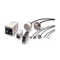 Separate Amplifier Sensor with Sensitivity Adjustment
Standard Models
Sensors
|
Model |
E2C-CR8A/ |
E2C-X1A/ |
E2C-X1R5A |
E2C-X2A |
E2C-X5A |
E2C-X10A |
E2C-C20MA |
|
|
Sensing distance |
1.8 mm |
2 mm |
3 mm |
5 mm |
10 mm |
18 mm |
50 mm |
|
|
Stable |
Ambient |
0 to 0.8 mm |
0 to 1 mm |
0 to 1.5 mm |
0 to 2 mm |
0 to 5 mm |
0 to 10 mm |
0 to 20 mm |
|
At 0 to 40°C |
0 to 1.2 mm |
0 to 1.5 mm |
0 to 2 mm |
0 to 2.5 mm |
0 to 7 mm |
0 to 15 mm |
0 to 28 mm |
|
|
Differential travel |
Refer to the amplifier unit specifications below. |
|||||||
|
Detectable object |
Ferrous metal (The sensing distance decreases with non-ferrous metal. Refer to Data Sheet.) |
|||||||
|
Standard sensing object |
Iron, 5 × 5 × 1 mm |
Iron, 8 × |
Iron, 12 × |
Iron, 18 × |
Iron, 30 × |
Iron, 50 × |
||
|
Response |
1 kHz |
800 Hz |
350 Hz |
100 Hz |
50 Hz |
|||
|
Ambient |
Operating/Storage: -25 to 70°C (with no icing or condensation) |
|||||||
|
Ambient |
Operating/Storage: 35% to 95% (with no condensation) |
|||||||
|
Temperature |
15% max. of sensing distance at 23°C in the temperature range of -25 to 70°C |
|||||||
|
Vibration resistance |
Destruction: 10 to 55 Hz, 1.5-mm double amplitude for 2 hours each in X and Y directions |
|||||||
|
Shock resistance |
Destruction: 500 m/s2 3 times each in X and Y directions |
|||||||
|
Degree of protection |
IEC 60529 IP67, in-house standards: oil-resistant |
|||||||
|
Connection method *2 |
Pre-wired Models |
|||||||
|
High-frequency coaxial cable (Standard cable length: 3 m) |
||||||||
|
Weight |
Approx. 40 g |
Approx. 45 g |
Approx. 50 g |
Approx. 60 g |
Approx. 140 g |
Approx. 270 g |
Approx. 300 g |
|
|
Materials |
Case |
Stainless steel |
Brass |
|||||
|
Sensing |
ABS resin |
|||||||
|
Cable |
Polyethylene |
|||||||
|
Clamping |
--- |
Brass, nickel-plated (except E2C-C1A) |
||||||
|
Toothed |
--- |
Iron, zinc-plated (except E2C-C1A) |
||||||
|
Accessories |
--- |
|||||||
1. The minimum value when using the solid-state control output on the Amplifier Unit.
Measurement conditions are as follows: standard sensing object, a distance of twice the standard sensing object, and a set distance of half the sensing distance.
2. Refer to 6 for cable lengths when combining Amplifier Units and Sensors. The characteristic impedance of the high-frequency coaxial cable is 50 Ω.
Amplifier Units
|
Model |
E2C-GE4A |
E2C-GF4A |
E2C-JC4A |
E2C-AM4A |
E2C-AK4A |
|
|
Power supply |
12 to 24 VDC (10 to 30 VDC), ripple (p-p): 10% max. *1 |
100 to 240 VAC |
||||
|
Current |
25 mA max. |
45 mA max. |
50 mA max. |
55 mA max. |
||
|
Sensing distance |
20% min. of rated sensing distance with |
20% to 100% of rated sensing distance with 4-turn potentiometer |
||||
|
Differential travel |
Differential travel fixed (10% max. of sensing distance) |
1% to 5% of rated sensing distance |
||||
|
Response |
Solid- |
(Refer to the response frequency of the Proximity Sensor.) |
||||
|
Relay |
--- |
20 ms max. |
||||
|
Control |
Solid- |
NPN |
PNP |
NPN |
NPN/PNP output |
Transistor/ |
|
Relay |
--- |
Relay output, SPDT |
||||
|
Indicators |
Detection indicator (red) |
Detection indicator |
Detection indicator (red) (OPERATION) |
|||
|
Operation mode |
Changed with NO/NC switch. |
|||||
|
Self-diagnostic |
--- |
(E2C-JC4AP only) |
--- |
|||
|
Timer function |
--- |
OFF-delay: 40 ±10 ms |
--- |
|||
|
Cable length |
--- |
(E2C-JC4AP only) |
Mode switched with 4-position switch. |
|||
|
Ambient |
Operating/storage: -10 to 55°C (with no icing or condensation) |
|||||
|
Ambient |
Operating/Storage: 35% to 85% (E2C-JC4AP: 35% to 95%) (with no condensation) |
|||||
|
Temperature |
10% max. of sensing distance at 23°C in the temperature range of -10 to 55°C |
|||||
|
Voltage influence |
DC Models: ±1% max. of sensing distance at rated voltage in the rated voltage ±20% range |
|||||
|
Insulation |
50 MΩ min. (at 500 VDC) between current-carrying parts and case |
|||||
|
Dielectric |
DC Models: 1,000 VAC, 50/60 Hz for 1 min between current-carrying parts and case |
|||||
|
Vibration |
Destruction: 10 to 25 Hz, 2-mm |
Destruction: 10 to 55 |
Destruction: 10 to 25 Hz, 2-mm double |
|||
|
Shock resistance |
Destruction: 100 m/s2 3 times each in X, Y, and Z directions |
|||||
|
Life expectancy |
--- |
Mechanical: |
||||
|
Connection |
Terminal block |
Pre-wired Models |
Terminal block |
|||
|
Weight (packed |
Approx. 20 g |
E2C-JC4A: Approx. 50 g |
Approx. 140 g |
Approx. 250 g |
||
|
Accessories |
Instruction manual |
Caution labels, Mounting |
Instruction manual |
|||
1. A full-wave rectification power supply of 24 VDC ±10% (average value) can be used (except for the E2C-GE4[]).
2. The sensing distance range required to maintain performed is given for using the Amplifier Unit in combination with the Sensor.
3. Internal relay: G2R-14 DC 12V
4. The weight of the Connection Socket is not included.
Heat-resistant Models
Sensors
|
Model |
E2C-X1R5AH |
E2C-X2AH |
E2C-X5AH |
|
|
Detectable object |
Ferrous metal (The sensing distance decreases with non-ferrous metal, refer to Datasheet.) |
|||
|
Standard sensing object |
Iron, 8 × 8 × 1 mm |
Iron, 12 × 12 × 1 mm |
Iron, 18 × 18 × 1 mm |
|
|
Stable sensing area |
0 to 1.5 mm |
0 to 2 mm |
0 to 5 mm |
|
|
Differential travel |
0.04 mm max. |
0.1 mm max. |
||
|
Response frequency *1 |
300 Hz |
|||
|
Ambient temperature range |
Operating/Storage: -10 to 200°C (with no icing or condensation) |
|||
|
Ambient humidity range |
Operating/Storage: 35% to 95% (with no condensation) |
|||
|
Temperature influence |
±0.2%/°C |
|||
|
Vibration resistance |
Destruction: 10 to 55 Hz, 1.5-mm double amplitude for 2 hours each in X, Y, and Z directions |
|||
|
Shock resistance |
Destruction: 500 m/s2 3 times each in X, Y, and Z directions |
|||
|
Degree of protection |
IEC 60529 IP60 *2 |
|||
|
Connection method |
Pre-wired Models (Cable length: 3 m) |
|||
|
Weight (packed state) |
Approx. 50 g |
Approx. 60 g |
Approx. 140 g |
|
|
Materials |
Case |
Brass |
||
|
Sensing surface |
PEEK (polyether ether ketone) |
|||
|
Cable |
Fluorine resin |
|||
|
Clamping nut |
Brass, nickel-plated |
|||
|
Toothed washer |
Iron, zinc-plated |
|||
Note: Ratings and characteristic are given for 50% of the stable sensing area.
1. Measurement conditions are as follows: standard sensing object, a distance of twice the standard sensing object, and a set distance of half the sensing distance.
2. Do not operate the Sensor in areas exposed to water vapor because the enclosure is not waterproof.
Amplifier Units
|
Model |
E2C-JC4CH |
E2C-JC4DH |
E2C-JC4EH |
|
|
Power supply voltage *1 |
12 to 24 VDC (10 to 30 VDC), ripple (p-p): 10% max. |
|||
|
Current consumption |
45 mA max. |
|||
|
Sensing distance adjustment range *2 |
20% to 100% of rated sensing distance |
|||
|
Control |
Load current |
NPN open collector, 100 mA max. (30 VDC max.) |
||
|
Residual voltage |
0.8 V max. |
|||
|
Indicators |
Detection indicator (red) |
|||
|
Operation mode |
Changed with NO/NC switch. |
|||
|
Cable length compensation |
Switched between 3 and 5 m. |
|||
|
Ambient temperature range |
Operating/storage: -10 to 55°C (with no icing or condensation) |
|||
|
Ambient humidity range |
Operating/storage: 35% to 85% (with no condensation) |
|||
|
Temperature influence |
±0.08%/°C |
|||
|
Voltage influence |
±2% max. of sensing distance at rated voltage in the rated voltage ±20% range |
|||
|
Insulation resistance |
50 MΩ min. (at 500 VDC) between current-carrying parts and case |
|||
|
Dielectric strength |
1,000 VAC, 50/60 Hz for 1 min between current-carrying parts and case |
|||
|
Vibration resistance |
Destruction: 10 to 55 Hz, 1.5-mm double amplitude for 2 hours each in X, Y, and Z directions |
|||
|
Shock resistance |
Destruction: 100 m/s2 3 times each in X, Y, and Z directions |
|||
|
Degree of protection |
IEC 60529 IP20 |
|||
|
Connection method |
Pre-wired Models (Cable length: 2 m) |
|||
|
Weight (packed state) |
Approx. 80 g |
|||
|
Accessories |
Caution labels, Mounting Bracket, instruction manual |
|||
1. A full-wave rectification power supply of 24 VDC ±10% (average value) can be used.
2. The sensing distance range required to maintain performed is given for using the Amplifier Unit in combination with the Sensor.