


Chemical-resistant Proximity Sensor
E2KQ-X
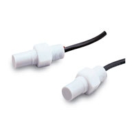 Fluororesin-coated Capacitive Sensor with Sensitivity Adjuster
|
Model |
E2KQ-X10ME1 |
E2KQ-X10ME2 |
|
|
Sensing distance *1 |
10 mm |
||
|
Sensing distance adjustable range |
6 to 10 mm |
||
|
Differential travel |
4% to 20% of sensing distance |
||
|
Detectable object |
Conductors and dielectrics |
||
|
Standard sensing object |
Grounded metal plate: 50 × 50 × 1 mm |
||
|
Response frequency |
35 Hz |
||
|
Power supply voltage |
12 to 24 VDC (10 to 30 VDC), ripple (p-p): 10% max. |
||
|
Current consumption |
15 mA max. |
||
|
Control output |
Load current |
100 mA |
|
|
Residual voltage |
1.5 V max. (Load current: 100 mA, Cable length: 2 m) |
||
|
Indicators |
Detection indicator (red) |
||
|
Operation mode |
NO |
NC |
|
|
Protection circuits |
Reverse polarity protection, Surge suppressor |
||
|
Ambient temperature range |
Operating: -10 to 55°C, Storage: -25 to 55°C (with no icing or condensation) |
||
|
Ambient humidity range |
Operating/storage: 35% to 85% (with no condensation) |
||
|
Temperature influence |
±15% max. of sensing distance at 23°C in the temperature range of -10 to 55°C |
||
|
Voltage influence |
±2% max. of sensing distance at rated voltage at rated voltage ±20% |
||
|
Insulation resistance |
50 MΩ min. (at 500 VDC) between current-carrying parts and case |
||
|
Dielectric strength |
500 VAC, 50/60 Hz for 1 min between current-carrying parts and case |
||
|
Vibration resistance |
Destruction: 10 to 55 Hz, 1.5-mm double amplitude for 2 hours each in X, Y, and Z directions |
||
|
Shock resistance |
Destruction: 500 m/s2 3 times each in X, Y, and Z directions |
||
|
Degree of protection |
IP66 (IEC), in-house standards: oil-resistant |
||
|
Connection method |
Pre-wired Models (Standard cable length: 2 m) |
||
|
Weight (packed state) |
Approx. 150 g |
||
|
Materials |
Case, |
Fluorine resin |
|
|
Clamping nuts |
|||
|
Cable |
Vinyl chloride |
||
|
Accessories |
Adjustment screwdriver, Instruction manual |
||
1. The above values are sensing distances for the standard sensing object. Refer to Engineering Data on the Data Sheet for other materials.
2. Refer to the timing charts under I/O Circuit Diagrams on Data Sheet for details.