


I/O Relay Terminal
G7TC
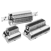 Single Cable Connection to PLC Means Space is Saved and Less Control Panel Wiring is Required.
Coil Ratings (Common to Input/Output per Relay)
Rated voltage (V) | Rated current (mA) | Coil resistance (Ω) | Must operate | Must release | Maximum voltage | Power consumption | |||
50 Hz | 60 Hz | of rated voltage | per Relay | per 16 Relays | |||||
AC | 100/(110) | 8.2/- | 7/7.7 | 8,700 | 80% max. | 30% min. | 105% | 0.7 VA | 11 VA |
200/(220) | 4.1/- | 3.5/3.85 | 33,300 | ||||||
DC | 12 | 42 | 290 | 80% max. | 10% min. | 105% | 0.5 W | 8 W | |
24 | 21 | 1,150 | |||||||
100/110 | 5 | 20,000 | |||||||
Note: 1. The rated current and coil resistance are measured at a coil temperature of 23°C with a tolerance of 15%/
-20% for AC rated current and ±15% for coil resistance.
2. The operating characteristics are measured at a coil temperature of 23°C.
3. The value for maximum voltage is the maximum value within the allowable voltage fluctuation range for the relay coil’s operating power supply. Continuous operation at this voltage is not within product specifications.
4. Approx. 4 mA flows into each LED indicator. To calculate the power supply capacity, add the current value of each LED indicator.
5. When the G7TC is used with an AC rated voltage, three rated currents can be used. If a coil voltage of 110 or 220 VAC is used, 50 Hz cannot be used.
Contact Ratings (G7T I/O Relay)
Classification | For input | For output | ||
Resistive load (cosφ=1) | Inductive load (cosφ=0.4 L/R=7 ms) | Resistive load (cosφ=1) | Inductive load (cosφ=0.4 L/R=7 ms) | |
Rated load | 1 A at 24 VDC | 0.5 A at 24 VDC | 2 A at 220 VAC 5 A at 24 VDC | 1 A at 220 VAC 2 A at 24 VDC |
Rated carry current | 1A | 5A | ||
Max. switching voltage | 250 VAC, 125 VDC | |||
Max. switching current | 1A | 0.5A | 5A | 2A |
Error rate (reference value) * | 100 μA at 1 V | 10 mA at 5 V | ||
Electrical endurance | 10,000,000 operations (at 10 mA) 50,000 operations (at 1 A) | 2,500,000 operations (at 10 mA) 20,000 operations (at 1 A) | 1,000,000 operations (under rated load) | |
Mechanical endurance | 50,000,000 operations | |||
* The above values are for a switching frequency of 120 operations/min.
Characteristics
Model | G7TC-IA16 (Input, AC coil) | G7TC-ID16 (Input, DC coil) | G7TC-OC16(-1) (output, DC coil) | G7TC-OC08 (output, DC coil) | |
Contact form | SPST-NO × 16 | SPST-NO × 8 | |||
Contact mechanism | Bifurcated crossbar contact | Single contact | |||
Contact material | Au cladding + Ag | AgInSn | |||
Contact resistance *1 | 50 mΩ max. | ||||
Must Operate time *2 | 15 ms max. | ||||
Release time *2 | 15 ms max. | ||||
Max. switching frequency | Mechanical limit | 18,000 operations/h | |||
At rated load | 1,800 operations/h | ||||
Insulation resistance | 100 MΩ (at 500 VDC) | ||||
Dielectric strength | Between coil and contact | 2,000 VAC, 50/60 Hz for 1 minute | |||
Between same polarity contacts | 1,000 VAC, 50/60 Hz for 1 minute | ||||
Between paired connectors *3 | 250 VAC, 50/60 Hz for 1 minute | ||||
Vibration resistance | 10 to 55 to 10 Hz with 0.5-mm single amplitude (1.0-mm double amplitude) | ||||
Shock resistance | 200 m/s2 | ||||
Noise immunity | Noise level: 1.5 kV; pulse width: 100 ns to 1μs | ||||
Rated voltage between positive and negative terminal blocks | Rated voltage of controller's (PLC or other) input circuit | 12 VDC ±5% 24 VDC ±5% | |||
Rated current between positive and negative terminal blocks | Input circuit current of controller (PLC or other) × number of ON points | 12 VDC: 46 mA × number of ON points 24 VDC: 25 mA × number of ON points | |||
Cable length *4 | To controller | 5 m max. (reference value) | |||
To I/O devices | 50 m max. (reference value, for 2-mm2 CVV cable) | Dependent on load | |||
Ambient operating temperature | 0 to 55°C | ||||
Ambient operating humidity | 35% to 85% (with no icing or condensation) | ||||
Tightening torque for external connections | 0.78 to 1.18 Nm | ||||
Tensile strength | No damage when a tensile force of 49 N is applied in each direction. In the direction of the track, the tensile strength is 9.8 N min. | ||||
I/O terminal tightening torque | Tightening strength: 0.98 Nm; Tensile strength 49 N per minute | ||||
LED color | Red | Green | |||
Case color | Transparent red | Transparent green | Transparent green | ||
Coil surge absorber | Varistor | Diode (1 A, 1,000 V) | |||
Weight | Approx. 640 g | Approx. 630 g | Approx. 670 g | Approx. 350 g | |
Note: The above values are initial values.
*1. Measurement: 1 A at 5 VDC.
*2. Ambient temperature: 23°C.
*3. This is between connector pin No. 10 and 20, and between connector pin No. 9 and 19.
*4. Connecting cables up to 5 m are available as standard products. For longer cables, enquire separately.
*1. Measurement: 1 A at 5 VDC.
*2. Ambient temperature: 23°C.
*3. This is between connector pin No. 10 and 20, and between connector pin No. 9 and 19.
*4. Connecting cables up to 5 m are available as standard products. For longer cables, enquire separately.
Approved Standards
• The rated values for safety standard certification are not the same as individually defined performance values. Always check the specifications before use.
• Standard G7TC I/O Relay Terminal, except for the G7TC-OC16-1, have met UL and CSA standards (UL file no. E95399; CSA file no. LR35535).
• Standard G7TC I/O Relay Terminal, except for the G7TC-OC16-1, have met UL and CSA standards (UL file no. E95399; CSA file no. LR35535).
UL standard certification (File No. E95399)
Model | Standard number | Category | Listed/Recognized | Contact ratings |
G7TC-ID16 G7TC-IA16 | UL508 | NRAQ2 | Recognized | Terminal block side: 250 VAC max./point Connector side: 10 mA/point, 24 VDC |
G7TC-OC16 G7TC-OC08 | UL508 | NRAQ2 | Recognized | Terminal block side: Inductive load: 10 A, 250 VAC Resistive load: 10 A, 30 VDC Rated horsepower: 1/2 HP, 240 VAC |
CSA Standard (File No. LR35535)
Model | Standard number | Class number | Contact ratings |
G7TC-ID16 | CSA C22.2 No.14 | 3211 04 | 6 to 240 VAC 6 to 125 VDC |
G7TC-IA16 | |||
G7TC-OC16 | |||
G7TC-OC08 |
Accessories (Order Separately)
Socket
P7TF-05
Contact resistance | 10 mΩ max. (measured at 5 V DC, 1 A) |
Dielectric strength | 2,000 VAC for 1 minute |
Insulation resistance | 1,000 MΩ min. (at 500 V) |
Vibration resistance | 10 to 55 to 10 Hz, 0.5 mm single amplitude (1.0 mm double amplitude) |
Shock resistance | 1,000 m/s2 |
Ambient temperature | Operating: -40 to 70°C (with no icing or condensation) |
Ambient humidity | 5% to 85% |
Weight | Approx. 28 g |