


Latching Relay
MMK
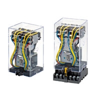 Mechanically Latching Relays Based on the MM Power Relay
Coil Ratings
Open Coils (with Solder or Screw Terminals)
Rated voltage (V) | Rated current (mA) | Coil resistance (Ω) | Must- operate voltage | Must- release voltage | Max. volt- age | Power consumption (VA or W) | ||||||
DP | 3P or 4P | DP | 3P or 4P | |||||||||
50 Hz | 60 Hz | 50 Hz | 60 Hz | % of rated voltage | Initial | Rated | ||||||
AC | 6 | 790 | 655 | 1,120 | 950 | 1.1 | 0.5 | 80% max. | 30% min. (60 Hz) 25% min. (50 Hz) | 110% | Approx. 4.1 (DP) Approx. 6.3 (3P or 4P) | Approx. 3.5 (DP) Approx. 5.1 (3P or 4P) |
12 | 395 | 325 | 560 | 480 | 4.7 | 2.0 | ||||||
24 | 195 | 160 | 280 | 240 | 19 | 8.5 | ||||||
50 | 94 | 78 | 134 | 114 | 82 | 36 | ||||||
100/(110) | 47 | 39/45 | 67 | 57/66 | 340 | 150 | ||||||
200/(220) | 23.5 | 19.5/22.5 | 33.5 | 28.5/33 | 1,540 | 620 | ||||||
DC | 6 | 340 | 450 | 17.5 | 13.4 | 70% max. | 10% min. | Approx. 2.1 (DP) Approx. 2.7 (3P or 4P) | ||||
12 | 176 | 220 | 68 | 54 | ||||||||
24 | 87 | 94 | 275 | 255 | ||||||||
48 | 41 | 52 | 1,180 | 930 | ||||||||
100/110 | 17/19 | 22/24.5 | 5,750 | 4,500 | ||||||||
200/220 | 8.6/9.5 | 11/12 | 23,200 | 18,000 | ||||||||
Note: 1. The rated current and coil resistance are measured at a coil temperature of 23°C with tolerances of +15%/-20% for AC rated current and ±15% for DC coil resistance.
2. The AC coil resistance values are reference values.
3. Performance characteristic data are measured at a coil temperature of 23°C.
4. The maximum voltage is one that is applicable instantaneously to the Relay coil at an ambient temperature of 23°C and not continuously.
2. The AC coil resistance values are reference values.
3. Performance characteristic data are measured at a coil temperature of 23°C.
4. The maximum voltage is one that is applicable instantaneously to the Relay coil at an ambient temperature of 23°C and not continuously.
Cased Coils (Plug-in Terminals)
The rated current may vary if the Relay has a built-in operating indicator (See note 4.).
Rated voltage (V) | Rated current (mA) | Coil resistance (Ω) | Coil inductance (H) | Must- oper- ate volt- age | Must- re- lease volt- age | Max. volt- age | Power con- sumption (VA or W) | |||||||||
DP | 3P or 4P | DP | 3P or 4P | DP | 3P or 4P | |||||||||||
50 Hz | 60 Hz | 50 Hz | 60 Hz | Con- tact re- lease | Con- tact oper- ate | Con- tact re- lease | Con- tact oper- ate | % of rated voltage | Ini- tial | Rated | ||||||
AC | 6 | 690 | 590 | 975 | 850 | 1.1 | 0.5 | 0.02 | 0.02 | 0.01 | 0.03 | 80% max. | 30% min. (60 Hz) 25% min. (50 Hz) | 110% | Ap- prox. 4.1 (DP) Ap- prox. 6.3 (3P or 4P) | Ap- prox. 3.5 (DP) Ap- prox. 5.1 (3P or 4P) |
12 | 345 | 295 | 490 | 430 | 4.7 | 2.0 | 0.07 | 0.01 | 0.04 | 0.07 | ||||||
24 | 170 | 145 | 245 | 210 | 19 | 8.5 | 0.28 | 0.41 | 0.18 | 0.28 | ||||||
50 | 82 | 70 | 117 | 102 | 82 | 36 | 1.2 | 1.7 | 0.75 | 1.2 | ||||||
100/ (110) | 41 | 35/ 40 | 58.5 | 51/ 58 | 340 | 150 | 4.8 | 6.7 | 3 | 4.5 | ||||||
200/ (220) | 20.5 | 17.5/ 20 | 29 | 25.5/ 29 | 1,540 | 620 | 20 | 25.6 | 12 | 19 | ||||||
DC | 6 | 340 | 450 | 17.5 | 13.4 | 0.2 | 0.36 | 0.23 | 0.35 | 70% max. | 10% min. | Approx. 2.1 (DP) Approx. 2.7 (3P or 4P) | ||||
12 | 176 | 220 | 68 | 54 | 0.74 | 1.0 | 0.87 | 1.4 | ||||||||
24 | 87 | 94 | 275 | 255 | 4.2 | 5.8 | 5.6 | 9.2 | ||||||||
48 | 41 | 52 | 1,180 | 930 | 20.4 | 26 | 27.3 | 45.5 | ||||||||
100/ 110 | 17/19 | 22/24.5 | 5,750 | 4,500 | 81.6 | 92.5 | 61.4 | 96.5 | ||||||||
200/ 220 | 8.6/9.5 | 11/12 | 23,200 | 18,000 | 340 | 380 | 158 | 250 | ||||||||
Note: 1. The rated current and coil resistance are measured at a coil temperature of 23°C with tolerances of +15%/-20% for AC rated current and ±15% for DC coil resistance.
2. The AC coil resistance and coil inductance values are for reference only.
3. Performance characteristic data are measured at a coil temperature of 23°C.
4. The maximum voltage is one that is applicable instantaneously to the Relay coil at an ambient temperature of 23°C and not continuously.
5. The rated current of a model with a built-in LED indicator at 6, 12, 24, or 50 VAC or 6, 12, 24, or 48 VDC increases by approx. 10 mA due to the current consumption of the LED. The rated current of a model with a built-in neon lamp indicator at 100/(110) or 200/(220) VAC or 100/110 or 200/220 VDC increases by approx. 0.2 mA due to the current consumption of the neon lamp.
Coils (Conforming to Auxiliary Power Relay Specifications)
Rated voltage (V) | Rated current (mA) | Coil re- sistance (Ω) | Coil inductance (H) | Must- operate voltage | Must- release voltage | Max. volt- age | Opera- tion level (JEC- 174D) | Power consumption (VA or W) | ||||
50 Hz | 60 Hz | Contact release | Contact operate | % of rated voltage | Initial | Rated | ||||||
AC | 24 | 245 | 210 | 8.5 | 0.18 | 0.28 | 80% max. | 30% min. (60 Hz) 25% min. (50 Hz) | 110% | B Hot start after coil heated | Approx. 6.3 | Approx. 5.1 |
50 | 117 | 102 | 36 | 0.75 | 1.2 | |||||||
100/ (110) | 58.5 | 51/58 | 150 | 3 | 4.5 | |||||||
110 | 53 | 46 | 182 | 3.6 | 5.5 | |||||||
115 | 51 | 44 | 210 | 4 | 6.2 | |||||||
200/ (220) | 29 | 25.5/29 | 620 | 12 | 19 | |||||||
220 | 26.5 | 23 | 780 | 15 | 21 | |||||||
DC | 24 | 94 | 255 | 5.6 | 9.2 | 70% max. | 10% min. | Approx. 2.7 | ||||
48 | 52 | 930 | 27.3 | 45.5 | ||||||||
100/ 110 | 22/24.5 | 4,500 | 61.4 | 96.5 | ||||||||
125 | 22 | 5,800 | 90 | 130 | ||||||||
200/ 220 | 11/12 | 18,000 | 158 | 250 | ||||||||
Note: 1. The rated current and coil resistance are measured at a coil temperature of 23°C with tolerances of +15%/-20% for AC rated current and ±15% for DC coil resistance.
2. The AC coil resistance and coil inductance values are for reference only.
3. Performance characteristic data are measured at a coil temperature of 23°C.
4. The maximum voltage is one that is applicable instantaneously to the Relay coil at 23°C and not continuously.
2. The AC coil resistance and coil inductance values are for reference only.
3. Performance characteristic data are measured at a coil temperature of 23°C.
4. The maximum voltage is one that is applicable instantaneously to the Relay coil at 23°C and not continuously.
Contact Ratings
Standard Relays
Item | Open Relays | Cased Relays | ||
MM2(B), MM3(B), MM4(B) | MM2P(N, -D), MM3P(N), MM4P(N, -D) | |||
Resistive load (cosφ = 1) | Inductive load (cosφ=0.4, L/R=7 ms) | Resistive load (cosφ = 1) | Inductive load (cosφ=0.4, L/R=7 ms) | |
Contact type | Single | |||
Contact material | Ag | |||
Rated load | 15 A at 220 VAC 10 A at 24 VDC | 7.5 A at 220 VAC 5 A at 24 VDC | ||
Rated carry current | 15 A | 7.5 A | ||
Max. switching voltage | 250 VAC, 250 VDC | 250 VAC, 250 VDC | ||
Max. switching current | 15 A | 7.5 A | ||
Max. switching power (reference value) | 3,300 VA at 240 W | 1,700 VA at 120 W | ||
Minimum permissible load (reference value) * | 5 VDC 10 mA | |||
* This value is measured at 60 operations/min.
DC-switching Relays/Built-in Diode Relays
Item | Open Relays | Cased Relays | ||
MM2X(B), MM3X(B), MM4X(B) | MM2XP(-D), MM3XP, MM4XP(-D) | |||
Resistive load (cosφ = 1) | Inductive load (L/R=7 ms) | Resistive load (cosφ = 1) | Inductive load (L/R=7 ms) | |
Contact type | Single | |||
Contact material | Ag | |||
Rated load | 10 A at 110 VDC | 7 A at 110 VDC | 7 A at 110 VDC | 6 A at 110 VDC |
Rated carry current | 15 A | 7.5 A | ||
Max. switching voltage | 250 VAC, 250 VDC | 250 VAC, 250 VDC | ||
Max. switching current | 15 A | 7.5 A | ||
Max. switching power (reference value) | 1,200 W at 20 VA *1 | 800 W at 20 VA *1 | 800 W at 20 VA *1 | 660 W at 20 VA *1 |
Minimum permissible load (reference value) *2 | 5 VDC at 10 mA | |||
Note: 1. When switching DC inductive loads at 125 V or more, an unstable region exists for a contact current of between 0.5 and 2.5 A. The Relay will not turn OFF in this region. Use a contact current of 0.5 A or less when switching 125 VDC or more.
2. If L/R exceeds 7 ms when switching DC inductive loads, an arc-breaking time of up to 50 ms must be considered in application and the circuit must be designed to ensure that an arc-breaking time of 50 ms is not exceeded.
3. The switching capacity for an AC load is minute.
*1. Refer to Switching an AC Load with a DC-switching Model ("X" Model) on Data Sheet.
*2. This value is measured at 60 operations/min.
Contacts (Conforming to Auxiliary Power Relay Specifications)
Item | MM4P-JD | MM4XP-JD | ||
Resistive load | Inductive load (cosΦ = 0.4, L/R = 7 ms) | Resistive load | Inductive load (cosΦ = 0.4, L/R = 7 ms) | |
Contact type | Single | |||
Contact material | Ag | |||
Rated load | 5 A at 220 VAC, 5 A at 24 VDC | 5 A at 110 VDC | ||
Rated carry current | 5 A | |||
Max. switching voltage | 250 VAC, 250 VDC | |||
Max. switching current | 5 A | |||
Max. switching power (reference value) | 1,100 VA, 120 W, 30 W (L/R = 40 ms) | 20 VA, 550 W, 40 W (L/R = 40 ms) | ||
Note: 1. A model for DC loads is not in stable operation when switching an inductive load within a operating current range between 0.5 and 2.5 A at a minimum of 125 VDC, where the load cannot be switched.
2. If L/R exceeds 7 ms when switching DC inductive loads, an arc-breaking time of up to 50 ms must be considered in application and the circuit must be designed to ensure that an arc-breaking time of 50 ms is not exceeded.
2. If L/R exceeds 7 ms when switching DC inductive loads, an arc-breaking time of up to 50 ms must be considered in application and the circuit must be designed to ensure that an arc-breaking time of 50 ms is not exceeded.
Characteristics
Standard Relays
Item | Open Relays | Cased Relays |
Contact resistance *2 | 25 mΩ max. | 50 mΩ max. |
Operate time *3 | AC: 25 ms max. DC: 50 ms max. | |
Release time *3 | 30 ms max. (100 ms max. for Built-in Diode Relays) | |
Max. operating frequency | Mechanical:7,200 operations/hr Electrical:1,800 operations/hr (under rated load) | |
Insulation resistance *4 | 100 MΩ min. (at 500 VDC) | |
Dielectric strength | 1,500 VAC, 50/60 Hz for 1 min between contacts of same polarity 2,000 VAC, 50/60 Hz for 1 min between contacts of different polarity (and between coil and contacts) | |
Vibration resistance | Destruction: 10 to 55 to 10 Hz, 0.75 mm single amplitude (1.5 mm double amplitude) Malfunction: 10 to 55 to 10 Hz, 0.5 mm single amplitude (1.0 mm double amplitude) | |
Shock resistance | Destruction: 1,000 m/s2 Malfunction: 100 m/s2 | |
Endurance | Mechanical: 5,000,000 operations min. (at 7,200 operations/hr) Electrical: 500,000 operations min. (at 1,800 operations/hr under rated load) *5 | |
Ambient temperature | Operating: -10°C to 55°C (with no icing or condensation) | |
Ambient humidity | Operating: 5% to 85% | |
Weight | Standard models: DC-switching models MM2 approx. 160 g MM2X approx. 165 g MM2XP approx. 225 g MM3 approx. 270 g MM3X approx. 275 g MM3XP approx. 395 g MM4 approx. 300 g MM4X approx. 310 g MM4XP approx. 420 g MM2P approx. 220 g MM3P approx. 360 g MM4P approx. 410 g | |
*1. The data shown above are initial values.
*2. The contact resistance was measured with 1 A at 5 VDC using the voltage drop method.
*3. The operate or release time was measured with the rated voltage imposed with any contact bounce ignored at an ambient temperature of 23°C.
*4. The insulation resistance was measured with a 500-VDC megger applied to the same places as those used for checking the dielectric strength.
*5. The electrical endurance was measured at an ambient temperature of 23°C.
Relays (Conforming to Auxiliary Power Relay Specifications)
Item | Cased Relays |
Contact resistance *2 | 50 mΩ max. |
Operate time *3 | AC: 25 ms max., DC: 50 ms max. |
Release time *3 | 30 ms max. |
Max. operating frequency | Mechanical: 1,800 operations/hr Electrical: 1,800 operations/hr (under rated load) |
Insulation resistance *4 | 100 MΩ min. |
Dielectric strength | Between coil and contact: 2,000 VAC, 50/60 Hz for 1 minute Between contacts of different polarity: 2,000 VAC, 50/60 Hz for 1 minute Between contacts of same polarity: 1,500 VAC, 50/60 Hz for 1 minute |
Vibration resistance | Destruction: 10 to 55 to 10 Hz, 0.75 mm single amplitude (1.5 mm double amplitude) Malfunction: 10 to 22 to 10 Hz, 0.5 mm single amplitude (1.0 mm double amplitude) |
Shock resistance | Destruction: 300 m/s2 Malfunction: 30 m/s2 |
Endurance | Mechanical: 5,000,000 operations min. (at 1,800 operations/hr) Electrical: 500,000 operations min. (at 1,800 operations/hr with rated load) *5 |
Error rate (level P) (Reference value) *6 | 10 mA at 5 VDC |
Ambient temperature | Operating: -10°C to 40°C (with no icing or condensation) |
Ambient humidity | Operating: 5% to 85% |
Weight | MM4P-JD: approx. 410 g MM4XP-JD: approx. 420 g |
*1. The data shown above are initial values.
*2. The contact resistance was measured with 1 A at 5 VDC using the voltage drop method.
*3. The operate or release time was measured with the rated voltage imposed with any contact bounce ignored at an ambient temperature of 23°C.
*4. The insulation resistance was measured with a 500-VDC megger applied to the same places as those used for checking the dielectric strength.
*5. The electrical endurance was measured at an ambient temperature of 23°C.
*6. This value was measured at a switching frequency of 60 operations per minute.