


Flat Inductive Proximity Sensor
TL-W
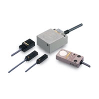 Standard Flat Sensors in Many Different Variations
DC 2-Wire Models
|
Model |
TL-W5MD[] |
|
|
Sensing distance |
5 mm ±10% |
|
|
Set distance |
0 to 4 mm |
|
|
Differential travel |
10% max. of sensing distance |
|
|
Detectable object |
Ferrous metal (The sensing distance decreases with non-ferrous metal. Refer to Engineering Data on |
|
|
Standard sensing object |
Iron, 18 × 18 × 1 mm |
|
|
Response frequency *1 |
500 Hz |
|
|
Power supply voltage |
12 to 24 VDC (10 to 30 VDC), ripple (p-p): 10% max. |
|
|
Leakage current |
0.8 mA max. |
|
|
Control |
Load current |
3 to 100 mA |
|
Residual voltage |
3.3 V max. (under load current of 100 mA with cable length of 2 m) |
|
|
Indicators |
D1 Models: Operation indicator (red), Setting indicator (green) |
|
|
Operation mode |
D1 Models: NO |
|
|
Protection circuits |
Load short-circuit protection, Surge suppressor |
|
|
Ambient temperature range |
Operating/Storage: -25 to 70°C (with no icing or condensation) |
|
|
Ambient humidity range |
Operating/Storage: 35% to 95% (with no condensation) |
|
|
Temperature influence |
±10% max. of sensing distance at 23°C in the temperature range of -25 to 70°C |
|
|
Voltage influence |
±2.5% max. of sensing distance at rated voltage in the rated voltage ±15% range |
|
|
Insulation resistance |
50 MΩ min. (at 500 VDC) between current-carrying parts and case |
|
|
Dielectric strength |
1,000 VAC for 1 min between current-carrying parts and case |
|
|
Vibration resistance |
Destruction: 10 to 55 Hz, 1.5-mm double amplitude for 2 hours each in X, Y, and Z directions |
|
|
Shock resistance |
Destruction: 500 m/s2 3 times each in X, Y, and Z directions |
|
|
Degree of protection |
IEC 60529 IP67, in-house standards: oil-resistant *2 |
|
|
Connection method |
Pre-wired Models (Standard cable length: 2 m) |
|
|
Weight (packed state) |
Approx. 80 g |
|
|
Materials |
Case |
Heat-resistant ABS |
|
Sensing surface |
||
|
Accessories |
Instruction manual |
|
1. The response frequency is an average value. Measurement conditions are as follows: standard sensing object, a distance of twice the standard sensing object, and a set distance of half the sensing distance.
2. For environments that require oil resistance, the upper limit of the ambient operating temperature range is 40°C.
DC 3-Wire Models
|
Model |
TL-W1R5MC1 |
TL-W3MC[] |
TL-W5MC[] |
TL-W5E1 |
TL-W20ME1 |
|
|
Sensing distance |
1.5 mm ±10% |
3 mm ±10% |
5 mm ±10% |
20 mm ±10% |
||
|
Set distance |
0 to 1.2 mm |
0 to 2.4 mm |
0 to 4 mm |
0 to 16 mm |
||
|
Differential travel |
10% max. of sensing distance |
1% to 15% of sensing distance |
||||
|
Detectable object |
Ferrous metal |
|||||
|
Standard sensing object |
Iron, |
Iron, |
Iron, |
Iron, |
||
|
Response frequency |
1 kHz min. |
600 Hz min. |
500 Hz min. |
300 Hz min. |
40 Hz min. |
|
|
Power supply voltage |
12 to 24 VDC (10 to 30 VDC), ripple (p-p): 10% max. |
12 to 24 VDC (10 to 30 VDC), ripple (p-p): 20% max. |
12 to 24 VDC (10 to 30 VDC), ripple (p-p): 10% max. |
|||
|
Current consumption |
15 mA max. at 24 VDC (no-load) |
10 mA max. at |
15 mA max. at |
8 mA at 12 VDC, |
||
|
Control |
Load |
TL-W1R5MC1/-W3MC[]: |
TL-W5MC[]: |
200 mA |
100 mA max. at 12 VDC |
|
|
Residual |
1 V max. (under load current of 100 mA with cable length of 2 m) |
2 V max. (under load current of 200 mA with cable length of 2 m) |
1 V max. (under load current of 200 mA with cable length of 2 m) |
|||
|
Indicators |
Detection indicator (red) |
|||||
|
Operation mode |
NO |
B1/C1 Models: NO |
E1/F1 Models: NO |
|||
|
Refer to the timing charts under I/O Circuit Diagrams on Data Sheet for details. |
||||||
|
Protection circuits |
Reverse polarity protection, Surge suppressor |
|||||
|
Ambient temperature |
Operating/Storage: -25 to 70°C (with no icing or condensation) * |
|||||
|
Ambient humidity range |
Operating/Storage: 35% to 95% (with no condensation) |
|||||
|
Temperature influence |
±10% max. of sensing distance at 23°C in the temperature range of -25 to 70°C |
|||||
|
Voltage influence |
±2.5% max. of sensing distance at rated voltage in the rated voltage ±10% range |
±2.5% max. of sensing distance at rated voltage in the rated voltage ±20% range |
±2.5% max. of sensing distance at rated voltage in the rated voltage ±10% range |
|||
|
Insulation resistance |
50 MΩ min. (at 500 VDC) between current-carrying parts and case |
|||||
|
Dielectric strength |
1,000 VAC, 50/60 Hz for 1 minute between current-carrying parts and case |
|||||
|
Vibration resistance |
Destruction: 10 to 55 Hz, 1.5-mm double amplitude for 2 hours each in X, Y, and Z directions |
|||||
|
Shock resistance |
Destruction: 500 m/s2 3 times each in X, Y, and Z directions |
Destruction: 500 m/s2 10 times each in X, Y, and Z directions |
||||
|
Degree of protection |
IEC 60529 IP67, in-house standards: oil-resistant * |
|||||
|
Connection method |
Pre-wired Models (Standard cable length: 2 m) |
|||||
|
Weight (packed state) |
Approx. 70 g |
Approx. 80 g |
Approx. 100 g |
Approx. 210 g |
||
|
Materials |
Case |
Heat-resistant ABS |
Aluminum die-cast |
Heat-resistant ABS |
||
|
Sensing |
Heat-resistant ABS |
|||||
|
Accessories |
Mounting Bracket, |
Instruction manual |
||||
For environments that require oil resistance, the upper limit of the ambient operating temperature range is 40°C.