


Floatless Level Switch (Basic Type)
61F-G[]
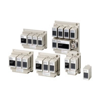 Basic Building-block Controllers That Mount Directly to Panels for Easier Maintenance
Standard Models
|
Items |
General-purpose |
High-temperature |
Long-distance Controllers |
|
Controlling materials |
For control of |
For control of ordinary |
For control of ordinary purified water in |
|
Supply voltage |
100, 110, 120, 200, 220 or 240 VAC; 50/60 Hz |
||
|
Operating voltage range |
85% to 110% of rated voltage |
||
|
InterElectrode voltage |
8 VAC |
||
|
InterElectrode current |
Approx. 1 mA AC max. |
||
|
Power consumption |
61F-G[]: 3.5 VA max.; G1F-G1[], G1F-G2[], or G1F-I[]: 5.5 VA max.; G1F-G3[]: 7.5 VA max.; |
||
|
InterElectrode operate |
0 to approx. 4 kΩ |
0 to approx. 5 kΩ |
0 to approx. 1.8 kΩ (for 2 km) |
|
InterElectrode release |
Approx. 15 k to ∞ Ω |
Approx. 15 k to ∞ Ω |
4 k to ∞ Ω (for 2 km) |
|
Cable length *3 |
1 km max. |
600 m max. |
2 km max. |
|
Control output |
2 A, 220 VAC (Inductive load: cosφΦ = 0.4) |
||
|
Ambient temperature |
Operating: -10 to 55°C (-10 to 70°C for 61F-[]T) |
||
|
Ambient humidity |
Operating: 45% to 85% RH |
||
|
Insulation resistance *4 |
100 MΩ min. (at 500 VDC) |
||
|
Dielectric strength *4 |
2000 VAC, 50/60 Hz for 1 min. |
||
|
Life expectancy |
Electrical: 500,000 operations min. |
||
|
Weight |
61F-G[]: Approx. 380 g, G1F-G1[], G1F-G2[], or G1F-I[]: Approx. 750 g; G1F-G3[]: Approx. |
||
|
Items |
High-sensitivity |
Low-sensitivity |
Two-wire Controller |
|
Controlling materials |
For control of liquids |
For control of liquids with |
For control of ordinary purified water |
|
Supply voltage |
100, 110, 120, 200, 220 or 240 VAC; 50/60 Hz |
||
|
Operating voltage range |
85% to 110% of rated voltage |
||
|
InterElectrode voltage |
24 VAC |
8 VAC |
|
|
InterElectrode current |
Approx. 1 mA AC max. |
||
|
Power consumption |
61F-G[]: 3.5 VA max.; G1F-G1[], G1F-G2[], or G1F-I[]: 5.5 VA max.; G1F-G3[]: 7.5 VA max.; |
||
|
InterElectrode operate |
Approx. 15 kΩ to |
0 to approx. 1.8 kΩ |
0 to approx. 1.1 kΩ |
|
InterElectrode release |
Approx. 300 k to ∞ Ω |
Approx. 5 k to ∞ Ω |
Approx. 15 k to ∞ Ω |
|
Cable length *3 |
50 m max. |
1 km max. |
800 m max. |
|
Control output |
2 A, 220 VAC (Inductive load: cosφΦ = 0.4) |
||
|
Ambient temperature |
Operating: -10 to 55°C (-10 to 70°C for 61F-[]T) |
||
|
Ambient humidity |
Operating: 45% to 85% RH |
||
|
Insulation resistance *4 |
100 MΩ min. (at 500 VDC) |
||
|
Dielectric strength *4 |
2000 VAC, 50/60 Hz for 1 min. |
||
|
Life expectancy |
Electrical: 500,000 operations min. |
||
|
Weight |
61F-G[]: Approx. 380 g, G1F-G1[], G1F-G2[], or G1F-I[]: Approx. 750 g; G1F-G3[]: Approx. |
||
1. The [] in the model name represents G, G1, G2, G3, G4, and I.
2. The suffix "TDL" attached to the model name represents models designed for tropical regions (storage humidity of 45% to 90%). For details, refer to Safety Precautions for Floatless Level Controllers.
3. The length when using completely-insulated, 600-V, 3-conductor (0.75 mm2) cabtire cables. Usable cable lengths will become shorter as the cable diameter or number of conductors becomes larger. For details, refer to Safety Precautions for Floatless Level Controllers.
4. The insulation resistance and dielectric strength indicate values between power terminals and Electrode terminals, between power terminals and contact terminals, and between Electrode terminals and contact terminals.
5. Possible to use with 15 kΩ or less, however, this may cause reset failure.
6. High-sensitivity Controllers use advanced operation. When the power supply voltage is applied, if there are some liquids between the electrodes (ground and operation electrodes), the internal relay will not operate. When the power supply voltage is applied, if there are no liquids between the electrodes (ground and operation electrodes), the internal relay will operate.
Advanced Operation
With advanced operation, the internal relay operates as soon as control power is supplied to the G1F and is reset when current flows between the poles. Wiring is the same as for models with sequential operation.