


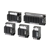
 Improved Design for a More Lightweight Construction and Reduced Standby Power Consumption.
Standard Models
|
Type |
General-purpose |
Long-distance |
High-sensitivity |
|
Controlling materials and |
For control of ordinary |
For control of ordinary |
For control of liquids with |
|
Rated voltage |
100/200, 110/220 or 120/240 VAC, 50/60 Hz (both supported on same model) |
||
|
Allowable voltage |
85% to 110% of rated voltage |
||
|
Inter-electrode voltage |
8 VAC |
||
|
Inter-electrode current |
Approx. 1 mA AC max. |
||
|
Power consumption |
GN[]: 3 VA max., G1N[], G2N[], IN[]: 4 VA max., G3N[]: 5.5 VA max., G4N[]: 8.5 VA max. |
||
|
Inter-electrode operation |
0 to approx. 4 kΩ |
0 to 1.8 kΩ (for 2 km) |
Approx. 10 kΩ to 40 kΩ |
|
Inter-electrode release |
Approx. 15 k to ∞Ω |
4 k to ∞Ω (for 2 km) |
Approx. 100 k to ∞Ω |
|
Cable length *2 |
1 km max. |
2 km max. |
50 m max. |
|
Output |
3 A, 200 VAC (Resistive load) |
||
|
Ambient operating |
- 10 to 55 °C |
||
|
Ambient operating humidity |
45% to 85% |
||
|
Insulation resistance *3 |
100 MΩ min. (at 500 VDC) |
||
|
Dielectric strength *3 |
2,000 VAC, 50/60 Hz for 1 min. |
||
|
Life expectancy |
Electrical: 250,000 operations min. |
||
|
Weight |
GN models: 315 g; G1N, G2N, IN models: 410 g; G3N models: 625g; G4N models: 870 g |
||
|
Internal Circuit Diagrams |
Example: 61F-GN |
Example: 61F-GNL
|
Example: 61F-GNH
|


1. The [] in the model name represents G, G1, G2, G3, G4, or I.
2. The length when using completely insulated, 600-V, 3-core (0.75 mm2) cabtire cables. Usable cable lengths will become shorter as the cable diameter or number of cores becomes larger due to increased floating capacity. For details, refer to Safety Precautions for Floatless Level Controllers.
3. The insulation resistance and dielectric strength are the values between power terminals and Electrode terminals, between power terminals and contact terminals, and between Electrode terminals and contact terminals. For details, refer to Safety Precautions for Floatless Level Controllers.
4. Application is possible with 10 kΩ or less, however, this may cause reset failures.
|
Type |
Low-sensitivity Controllers |
Two-wire Controllers |
|
Controlling materials and |
For control of liquids with low specific |
For control of ordinary purified water or |
|
Rated voltage |
100/200, 110/220 or 120/240 VAC, 50/60 Hz (supported by the same model) |
|
|
Allowable Voltage Fluctuation |
85% to 110% of rated voltage |
|
|
Inter-electrode voltage |
8 VAC |
|
|
Inter-electrode current |
Approx. 1 mA AC max. |
|
|
Power consumption |
GN[]: 3 VA max., G1N[], G2N[], IN[]: 4 VA max., G3N[]: 5.5 VA max., |
|
|
Inter-electrode operation |
0 to approx. 1.8 k |
Approx. 0 to 1.1 k |
|
Inter-electrode release |
Approx. 5 k to 0% |
Approx. 15 k to 0% |
|
Cable length *2 |
1 km max. |
800 m max. |
|
Output |
3 A, 200 VAC (Resistive load) |
|
|
Ambient operating temperature |
- 10 to 55 °C |
|
|
Ambient operating humidity |
45% to 85% |
|
|
Insulation resistance *3 |
100 MΩ min. (at 500 VDC) |
|
|
Dielectric strength *3 |
2,000 VAC, 50/60 Hz for 1 min. |
|
|
Life expectancy |
Electrical: 250,000 operations min. |
|
|
Weight |
GN models: 315 g; G1N, G2N, IN models: 410 g; G3N models: 625g; |
|
|
Internal Circuit Diagrams |
Example: 61F-GND
|
Example: 61F-GNR
|


1. The [] in the model name represents G, G1, G2, G3, G4, or I.
2. The length when using completely insulated, 600-V, 3-core (0.75 mm2) cabtire cables. Usable cable lengths will become shorter as the cable diameter or number of cores becomes larger due to increased floating capacity. For details, refer to Safety Precautions for Floatless Level Controllers.
3. The insulation resistance and dielectric strength are the values between power terminals and Electrode terminals, between power terminals and contact terminals, and between Electrode terminals and contact terminals. For details, refer to Safety Precautions for Floatless Level Controllers.
4. Application is possible with 10 kΩ or less, however, this may cause reset failures.