


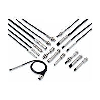
 Ultra small size, but surprisingly easy installation!
|
Size |
3 dia. |
4 dia. |
5.4 dia. |
|||||
|
Type |
Shielded |
Unshielded |
Shielded |
Unshielded |
Shielded |
|||
|
Model |
E2E- |
E2E- |
E2E- |
E2E- |
E2E- |
|||
|
Sensing distance |
0.8 mm |
2 mm |
1.2 mm |
3 mm |
1mm |
|||
|
Setting distance *1 |
0 to 0.56 |
0 to 1.4 |
0 to 0.84 |
0 to 2.1 |
0 to 0.7 |
|||
|
Differential travel |
15% max. of sensing distance |
|||||||
|
Detectable object |
Ferrous metal (The sensing distance decreases with non-ferrous metal. Refer to Engineering Data on Catalog.) |
|||||||
|
Standard sensing |
Iron, 3 × 3 |
Iron, 6 × 6 |
Iron, 4 × 4 |
Iron, 9 × 9 |
Iron, 5.4 × 5.4 |
|||
|
Response frequency *2 |
5 kHz |
3.5 kHz |
4 kHz |
2 kHz |
4 kHz |
|||
|
Power supply voltage *3 |
10 to 30 VDC (including 10% ripple (p-p)) |
|||||||
|
Current consumption |
10 mA max. |
|||||||
|
Control |
Load current |
50 mA max. |
100 mA max. |
|||||
|
Residual |
2 V max. *5 |
|||||||
|
Indicators |
Operation indicator: Yellow (complies with European standard EN60947-5-2) Lights during output. |
|||||||
|
Operation mode |
B1/B2: PNP open collector, C1/C2: NPN open collector |
|||||||
|
Protection circuits |
Output reverse polarity protection, Power source circuit reverse polarity protection, Surge suppressor, Load short-circuit protection |
|||||||
|
Ambient |
Operation and storage: -25 to 70°C (with no icing or condensation) |
|||||||
|
Ambient |
Operation and storage: 35% to 95% (with no condensation) |
|||||||
|
Temperature |
±15% max. of sensing distance at 23°C within temperature range of -25 to 70°C |
|||||||
|
Voltage influence |
±2.5% max. of sensing distance at rated voltage in the rated voltage ±15% range |
|||||||
|
Insulation resistance |
50 MΩ min. (at 500 VDC) between current-carrying parts and case |
|||||||
|
Dielectric strength |
500 VAC, 50/60 Hz for 1 minute between current-carrying parts and case |
|||||||
|
Vibration resistance |
Destruction: 10 to 55 Hz, 1.5-mm double amplitude for 2 hours each in X, Y, and Z directions |
|||||||
|
Shock resistance |
Destruction: 500 m/s2 10 times each in X, Y, and Z directions |
|||||||
|
Degree of protection |
IEC 60529 IP67, in-house standards: oil-resistant *6 |
|||||||
|
Con- |
Pre-wired |
Yes |
Yes |
Yes |
||||
|
M8 Pre-wired |
Yes |
Yes |
No |
|||||
|
M8 Connector |
No |
Yes |
No |
|||||
|
Weight |
Pre-wired |
Approx. |
Approx. |
Approx. |
Approx. |
Approx. |
||
|
M8 Pre-wired |
Approx. |
Approx. |
Approx. |
Approx. |
--- |
|||
|
M8 Connector |
--- |
--- |
Approx. |
Approx. |
--- |
|||
|
Materi- |
Case |
SUS303 (EN 1.4305) *7 |
Nickelplated |
|||||
|
Sensing |
Heat-resistant ABS |
|||||||
|
Clamping |
No |
|||||||
|
Toothed |
No |
|||||||
|
Cable |
Polyvinyl chloride (PVC) |
|||||||
|
Acces- |
Instruction |
Yes |
||||||
|
Model label |
Yes |
|||||||
|
Mounting |
Sold separately |
|||||||
|
Size |
6.5 dia. |
M4 |
M5 |
|||||
|
Type |
Shielded |
Unshielded |
Shielded |
Unshielded |
Shielded |
Unshielded |
||
|
Model |
E2E- |
E2E- |
E2E- |
E2E- |
E2E- |
E2E- |
||
|
Sensing distance |
2 mm |
4 mm |
0.8 mm |
2 mm |
1.2 mm |
3 mm |
||
|
Setting distance *1 |
0 to 1.4 |
0 to 2.8 |
0 to 0.56 |
0 to 1.4 |
0 to 0.84 |
0 to 2.1 |
||
|
Differential travel |
15% max. of sensing distance |
|||||||
|
Detectable object |
Ferrous metal (The sensing distance decreases with non-ferrous metal. Refer to Engineering Data on Catalog.) |
|||||||
|
Standard sensing |
Iron, 6.5 × 6.5 |
Iron, 12 × 12 |
Iron, 3 × 3 |
Iron, 6 × 6 |
Iron, 4 × 4 |
Iron, 9 × 9 |
||
|
Response frequency *2 |
3 kHz |
3 kHz |
5 kHz |
3.5 kHz |
4 kHz |
2 kHz |
||
|
Power supply voltage *3 |
10 to 30 VDC (including 10% ripple (p-p)) |
|||||||
|
Current consumption |
10 mA max. |
|||||||
|
Control |
Load current |
200 mA max. |
50 mA max. |
100 mA max. |
||||
|
Residual |
2 V max. *5 |
|||||||
|
Indicators |
Operation indicator: Yellow (complies with European standard EN60947-5-2) Lights during output. |
|||||||
|
Operation mode |
B1/B2: PNP open collector, C1/C2: NPN open collector |
|||||||
|
Protection circuits |
Output reverse polarity protection, Power source circuit reverse polarity protection, Surge suppressor, Load short-circuit protection |
|||||||
|
Ambient |
Operation and storage: -25 to 70°C (with no icing or condensation) |
|||||||
|
Ambient |
Operation and storage: 35% to 95% (with no condensation) |
|||||||
|
Temperature |
±15% max. of sensing distance at 23°C within temperature range of -25 to 70°C |
|||||||
|
Voltage influence |
±2.5% max. of sensing distance at rated voltage in the rated voltage ±15% range |
|||||||
|
Insulation resistance |
50 MΩ min. (at 500 VDC) between current-carrying parts and case |
|||||||
|
Dielectric strength |
500 VAC, 50/60 Hz for 1 minute between current-carrying parts and case |
|||||||
|
Vibration resistance |
Destruction: 10 to 55 Hz, 1.5-mm double amplitude for 2 hours each in X, Y, and Z directions |
|||||||
|
Shock resistance |
Destruction: 500 m/s2 10 times each in X, Y, and Z directions |
|||||||
|
Degree of protection |
IEC 60529 IP67, in-house standards: oil-resistant *6 |
|||||||
|
Con- |
Pre-wired |
Yes |
Yes |
Yes |
||||
|
M8 Pre-wired |
Yes |
Yes |
Yes |
|||||
|
M8 Connector |
Yes |
No |
Yes |
|||||
|
Weight |
Pre-wired |
Approx. |
Approx. |
Approx. |
Approx. |
Approx. |
Approx. |
|
|
M8 Pre-wired |
Approx. |
Approx. |
Approx. |
Approx. |
Approx. |
Approx. |
||
|
M8 Connector |
Approx. |
Approx. |
--- |
--- |
Approx. |
Approx. |
||
|
Materi- |
Case |
SUS303 (EN 1.4305) *7 |
||||||
|
Sensing |
Heat-resistant ABS |
|||||||
|
Clamping |
No |
SUS430 (EN 1.4016) *7 |
||||||
|
Toothed |
No |
SUS303 (EN 1.4305) *7 |
||||||
|
Cable |
Polyvinyl chloride (PVC) |
|||||||
|
Acces- |
Instruction |
Yes |
||||||
|
Model label |
Yes |
|||||||
|
Mounting |
Sold separately |
|||||||
1. Using within the set distance enables high-speed responsiveness and a more stable repeat accuracy.
2. The response frequency is an average value.
3. When used at a power of 12 V, the Sensor is less susceptible to the effects of internal self heat generation and
therefore a more stable repeat accuracy can be obtained.
4. When the control output is 20 mA or less, the Sensor is less susceptible to the effects of internal self heat
generation and therefore a more stable repeat accuracy can be obtained.
5. 3 dia., M4: load current 50 mA, cable length 2 m
4 dia., 5.4 dia., M5: load current 100 mA, cable length 2 m
6.5 dia.: load current 200 mA, cord length 2 m
6. Oil resistance in-house standard: Performance with respect to water insoluble oil. (Test at right)
7. Material name in EN standards.
8. Clamping nuts: 2 pieces, toothed washer: 1 piece
Oil resistance test

After the test time elapses, the characteristics below are checked for problems.
(1) Visual appearance (no damage that affects product characteristics)
(2) Operation check (ON/OFF)
(3) Insulation resistance (50 MΩ min. at 500 VDC)
(4) Dielectric strength (500 VAC, 1 min.)
(5) Water resistance (IP67)