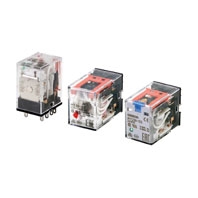
Miniature Power Relays
MY-GS
 Mechanical Indicators Added as a Standard Feature to Our Best-selling MY General-purpose Relays
Model Number Structure
Model Number Legend
List of Models
Miniature Power Relays (MY-GS-R)
Category | Number of poles | Contact structure | Plug-in (octal pins) terminals | ||
With operation indicator | |||||
With latching lever | |||||
Standard models | 2 | Single | MY2-GS-R | MY2N-GS-R | MY2IN-GS-R |
4 | MY4-GS-R | MY4N-GS-R | MY4IN-GS-R | ||
Models with built-in diodes for coil surge absorption | 2 | --- | MY2N-D2-GS-R | MY2IN-D2-GS-R | |
4 | --- | MY4N-D2-GS-R | MY4IN-D2-GS-R | ||
Models with built-in CR circuits for coil surge absorption | 2 | --- | MY2N-CR-GS-R | MY2IN-CR-GS-R | |
4 | --- | MY4N-CR-GS-R | MY4IN-CR-GS-R | ||
Ordering Information
Main unit
Standard model without operation indicator
Number of poles | Model | Rated voltage (V) |
2 | MY2-GS-R | 12, 24, 48, 100/110, 110/120, 200/220, 220/240 VAC 6, 12, 24, 48, 100/110 VDC |
4 | MY4-GS-R | 12, 24, 48, 100/110, 110/120, 200/220, 220/240 VAC 6, 12, 24, 48, 100/110 VDC |
Standard model with operation indicator
Number of poles | Model | Rated voltage (V) |
2 | MY2N-GS-R | 12, 24, 48, 100/110, 110/120, 200/220, 220/240 VAC 6, 12, 24, 48, 100/110, 220 VDC |
4 | MY4N-GS-R | 12, 24, 48, 100/110, 110/120, 200/220, 220/240 VAC 6, 12, 24, 48, 100/110, 220 VDC |
Standard model with operation indicator and latching lever
Number of poles | Model | Rated voltage (V) |
2 | MY2IN-GS-R | 12, 24, 48, 100/110, 110/120, 200/220, 220/240 VAC 6, 12, 24, 48, 100/110, 220 VDC |
4 | MY4IN-GS-R | 12, 24, 48, 100/110, 110/120, 200/220, 220/240 VAC 6, 12, 24, 48, 100/110, 220 VDC |
Models with built-in diodes for coil surge absorption with operation indicator
Number of poles | Model | Rated voltage (V) |
2 | MY2N-D2-GS-R | 12, 24, 48, 100/110, 220 VDC |
4 | MY4N-D2-GS-R | 12, 24, 48, 100/110, 220 VDC |
Models with built-in diodes for coil surge absorption with operation indicator and latching lever
Number of poles | Model | Rated voltage (V) |
2 | MY2IN-D2-GS-R | 12, 24, 48, 100/110, 220 VDC |
4 | MY4IN-D2-GS-R | 12, 24, 48, 100/110, 220 VDC |
Models with built-in CR circuits for coil surge absorption with operation indicator
Number of poles | Model | Rated voltage (V) |
2 | MY2N-CR-GS-R | 100/110, 110/120, 200/220, 220/240 VAC |
4 | MY4N-CR-GS-R | 100/110, 110/120, 200/220, 220/240 VAC |
Models with built-in CR circuits for coil surge absorption with operation indicator and latching lever
Number of poles | Model | Rated voltage (V) |
2 | MY2IN-CR-GS-R | 100/110, 110/120, 200/220, 220/240 VAC |
4 | MY4IN-CR-GS-R | 100/110, 110/120, 200/220, 220/240 VAC |
Common Options (Order Separately)
Ordering Information
Front-mounting Sockets
Number of Pins | Applicable Relay Model | Terminal Type | Mounting Method | Appearance | Model | Hold-down Clips |
8 | MY2-GS-R MY2N-GS-R MY2IN-GS-R MY2N-D2-GS-R MY2IN-D2-GS-R MY2N-CR-GS-R MY2IN-CR-GS-R | Screw terminal Finger protection structure *1 (Screw size M3) | DIN Track or screw mounting | PYFZ-08-E | PYC-A1 *3 | |
Screw terminal Finger protection structure *1 (Screw size M3) | DIN Track or screw mounting | PYF08A-N | PYC-A1 *3 | |||
Push-In Plus Terminal (Integrated Socket with release lever) | DIN Track or screw mounting *2 | PYF-08-PU | --- | |||
14 | MY4-GS-R MY4N-GS-R MY4IN-GS-R MY4N-D2-GS-R MY4IN-D2-GS-R MY4N-CR-GS-R MY4IN-CR-GS-R | Screw terminal Finger protection structure *1 (Screw size M3) | DIN Track or screw mounting | PYFZ-14-E | PYC-A1 *3 | |
Screw terminal Finger protection structure *1 (Screw size M3) | DIN Track or screw mounting | PYF14A-N | PYC-A1 *3 | |||
Push-In Plus Terminal (Integrated Socket with release lever) | DIN Track or screw mounting *2 | PYF-14-PU | --- |
*1. In the finger protection type (PYFZ-[]-E, and PYF[]A-N), the terminal cover is integrated into the Socket.
Round terminals cannot be used.
Use forked terminals or ferrules instead.
*2. There are screw mounting holes in the DIN hooks on the PYF-[][]-PU. Pull out the DIN hook tabs to mount the Sockets
with screws.
*3. Model number of the applicable Mounting Bracket. Sold in sets of two.
Round terminals cannot be used.
Use forked terminals or ferrules instead.
*2. There are screw mounting holes in the DIN hooks on the PYF-[][]-PU. Pull out the DIN hook tabs to mount the Sockets
with screws.
*3. Model number of the applicable Mounting Bracket. Sold in sets of two.
Back-mounting Sockets
Number of Pins | Applicable Relay Model | Terminal Type | Appearance | Model | Hold-down Clips |
8 | PY08-02 | PCB terminals | PY08-02 | PYC-P | |
14 | PY14-02 | PCB terminals | PY14-02 |
Socket accessories
Mounting Bracket
Mounting Bracket
Appearance *1 | Model | Weight *2 | Application |
PYC-A1 | Approx. 0.54 g | For joining the Socket and Relay | |
PYC-P | Approx. 1.4 g | For joining the Socket and Relay |
*1. Describes the appearance when the Relay, Socket, and Mounting Bracket have been combined together.
*2. The PYC-A1 includes two Mounting Brackets in one set. The weight specified above is the weight of one Mounting
Bracket.
*2. The PYC-A1 includes two Mounting Brackets in one set. The weight specified above is the weight of one Mounting
Bracket.


