


Miniature Power Relays
MY-GS
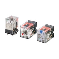 Mechanical Indicators Added as a Standard Feature to Our Best-selling MY General-purpose Relays
Ratings
Main unit
Operating Coil
Item | Rated current (mA) | Coil resis- tance (Ω) | Coil inductance (H) | Must- operate voltage | Must- release voltage | Maxi- mum voltage | Power consumption (VA, W) | |||
Rated voltage | 50 Hz | 60 Hz | Armature OFF | Armature ON | Percentage of rated voltage | |||||
AC | 12 | 106.5 | 91 | 46 | 0.17 | 0.33 | 80% max. *1 | 30% min. *2 | 110% | Approx. 0.9 to 1.3 (at 60 Hz) |
24 | 53.8 | 46 | 180 | 0.69 | 1.3 | |||||
48 | 25.7 | 21.1 | 788 | 3.22 | 5.66 | |||||
100/110 | 11.7/12.9 | 10.0/11.0 | 3,750 | 14.54 | 24.6 | |||||
110/120 | 9.9/10.8 | 8.4/9.2 | 4,430 | 19.2 | 32.1 | |||||
200/220 | 6.2/6.8 | 5.3/5.8 | 12,950 | 54.75 | 94.07 | |||||
220/240 | 5.2/6.2 | 4.3/5.0 | 15,920 | 83.5 | 136.4 | |||||
DC | 6 | 146 (151) | 41.0 (39.8) | 0.17 | 0.33 | 10% min. *2 | Approx. 0.9 | |||
12 | 72.7 (75) | 165 (160) | 0.73 | 1.37 | ||||||
24 | 36.3 (37.7) | 662 (636) | 3.2 | 5.72 | ||||||
48 | 17.6 (18.8) | 2,725 (2,560) | 10.6 | 21.0 | ||||||
100/110 | 8.7 (9.0)/9.6 (9.9) | 11,440 (11,100) | 45.6 | 86.2 | ||||||
220 | 3.6 | 60,394 | 362.3 | 452.9 | Approx. 0.8 | |||||
Note:
1. The rated current and coil resistance are measured at a coil temperature of 23°C with tolerances of +15%/−20% for the AC rated current and +15% for the DC coil resistance.
2. The AC coil resistance and inductance values are reference values only (at 60 Hz).
3. Operating characteristics were measured at a coil temperature of 23°C.
4. The values in parentheses for the rated currents and coil voltages of DC coils are for models with LED operation indicators.
5. The maximum voltage capacity was measured at an ambient temperature of 23°C.
*1. There is variation between products, but actual values are 80% max.
The Relay will operate if 80% or higher of the rated voltage is applied. However, to achieve the specified characteristics, apply the rated voltage to the coil.
*2. There is variation between products, but actual values are 30% minimum for AC and 10% minimum for DC. To ensure release, use a value that is lower than the specified value.
Contacts
2 poles | 4 poles | |||||
Resistive load | Inductive load (cos φ = 0.4, L/R = 7 ms) | Resistive load | Inductive load (cos φ = 0.4, L/R = 7 ms) | |||
Contact configuration | DPDT | 4PDT | ||||
Contact structure | Single | |||||
Contact material | Ag | |||||
Rated load | 10 A at 250 VAC 10 A at 30 VDC | 5 A at 220 VDC 5 A at 24 VDC | 2 A at 220 VAC 2 A at 24 VDC | 6 A at 250 VDC 6 A at 30 VDC | 3 A at 220 VDC 3 A at 24 VDC | 0.8 A at 220 VAC 1.5 A at 24 VDC |
Electrical endurance *1 | 100,000 operations | 500,000 operations | 30,000 operations | 200,000 operations | ||
Rated carry current *2 | 10 A | 6 A *2 | ||||
Maximum contact voltage | 250 VAC, 220 VDC | 250 VAC, 220 VDC | ||||
Maximum contact current *2 | 10 A | 6 A *2 | ||||
Maximum switching capacity | 2,500 VA 300 W | 440 VA 48 W | 1,500 VA 180 W | 176 VA 36 W | ||
Minimum load (reference values) *3 | 1 mA at 5 VDC | |||||
*1. Rated load, switching frequency: 2,400 operations/h. Ambient temperature condition: 23°C. Duty ratio: 33%.
*2. 4 poles of 6 A is for an ambient temperature of 50°C. At an ambient temperature of 70°C, the value is 3 A.
*3. These values are guides for the switchable limits for minute load levels, such as in electronic circuits. Actual
characteristics may be different.
*2. 4 poles of 6 A is for an ambient temperature of 50°C. At an ambient temperature of 70°C, the value is 3 A.
*3. These values are guides for the switchable limits for minute load levels, such as in electronic circuits. Actual
characteristics may be different.
These values will depend on the switching frequency, atmosphere, and expected reliability level. Confirm applicability
in the actual system under actual application conditions.
in the actual system under actual application conditions.
Characteristics
Main unit
2 poles | 4 poles | ||
Contact resistance *1 | 100 mΩ max. | ||
Operation time *2 | 20 ms max. | ||
Release time *2 | 20 ms max. | ||
Maximum operating frequency | Mechanical | 18, 000 operations/h | |
Rated load | 2,400 operations/h | ||
Insulation resistance *3 | 1,000 MΩ min. | ||
Dielectric strength | Between coil and contacts | 2,000 VAC at 50/60 Hz for 1 min. | |
Between contacts of different polarity | 2,000 VAC at 50/60 Hz for 1 min. | ||
Between contacts of the same polarity | 1,000 VAC at 50/60 Hz for 1 min. | ||
Vibration resistance | Destruction | 10 to 55 to 10 Hz, Double amplitude: 1.0 mm | |
Malfunction | 10 to 55 to 10 Hz, Double amplitude: 1.0 mm | ||
Shock resistance | Destruction | 1,000 m/s2 (approx. 100 G) | |
Malfunction | 200 m/s2 (Approx. 20 G) | ||
Mechanical endurance | 50,000,000 operations (switching frequency: 18,000 operations/h) | ||
Ambient operating temperature | Standard models: -55 to 70°C (with no icing or condensation) Models with LED operation indicators: -40 to 70°C (with no icing or condensation) | ||
Ambient humidity | 5% to 85% | ||
Weight | Approx. 35 g | ||
Note: The above values are initial values.
*1. Measurement conditions: 1 A at 5 VDC using the voltage drop method.
*2. Measurement conditions: With rated operating power applied, not including contact bounce time.
*3. Measurement conditions: For 500 VDC applied to the same location as for dielectric strength measurement.
*1. Measurement conditions: 1 A at 5 VDC using the voltage drop method.
*2. Measurement conditions: With rated operating power applied, not including contact bounce time.
*3. Measurement conditions: For 500 VDC applied to the same location as for dielectric strength measurement.
Options (order separately)
Sockets
Model | Con- nec- tion | Num- ber of Pins | Ter- minal Type | Ambi- ent operat- ing tem- pera- ture | Am- bient hu- midity | Con- tinuous carry current | Dielectric strength | Insu- lation re- sistance *1 | Weight | ||
Between contact termi- nals of same polarity | Between contact termi- nals of different polarity | Between coil and contact termi- nals | |||||||||
PYFZ-08-E | Front | 8 | Screw termi- nal | -55 to 70°C | 5% to 85% RH | 10 A | 2,250 VAC 1 min | 2,250 VAC 1 min | 2,250 VAC 1 min | 1,000 MΩ min. (500 VDC) | Approx. 32 g |
PYF08A-N | -55 to 55°C | 5% to 85% RH | 7A *3 | 2,000 VAC 1 min | 2,000 VAC 1 min | 2,000 VAC 1 min | 1,000 MΩ min. (500 VDC) | Approx. 32 g | |||
PYF-08-PU | Push- In Plus Termi- nal | -40 to 70°C | 5% to 85% RH | 10A *2 | 2,000 VAC 1 min | 2,000 VAC 1 min | 2,000 VAC 1 min | 1,000 MΩ min. (500 VDC) | Approx. 80 g | ||
PYFZ-14-E | 14 | Screw termi- nal | -55 to 70°C | 5% to 85% RH | 6A | 2,250 VAC 1 min | 2,250 VAC 1 min | 2,250 VAC 1 min | 1,000 MΩ min. (500 VDC) | Approx. 50 g | |
PYF14A-N | -55 to 55°C | 5% to 85% RH | 5A *3 | 2,000 VAC 1 min | 2,000 VAC 1 min | 2,000 VAC 1 min | 1,000 MΩ min. (500 VDC) | Approx. 50 g | |||
PYF-14-PU | Push- In Plus Termi- nal | -40 to 70°C | 5% to 85% RH | 6A | 2,000 VAC 1 min | 2,000 VAC 1 min | 2,000 VAC 1 min | 1,000 MΩ min. (500 VDC) | Approx. 87 g | ||
PY08-02 | Back | 8 | PCB termi- nals | -55 to 70°C | 5% to 85% RH | 7A | 1,500 VAC 1 min | 1,500 VAC 1 min | 1,500 VAC 1 min | 100 MΩ min. | Approx. 7.2 g |
PY14-02 | 14 | -55 to 70°C | 5% to 85% RH | 3A | 1,500 VAC 1 min | 1,500 VAC 1 min | 1,500 VAC 1 min | 100 MΩ min. | Approx. 10 g | ||
*1. For 500 VDC applied to the same location as for dielectric strength measurement.
*2. The continuous carry current of 10 A is for an ambient temperature of 55°C. At an ambient temperature of 70°C, the value is 7 A.
*3. When using the PYF08A-N or PYF14A-N at an ambient operating temperature exceeding 40°C, reduce the continuous carry current to 60%.
*2. The continuous carry current of 10 A is for an ambient temperature of 55°C. At an ambient temperature of 70°C, the value is 7 A.
*3. When using the PYF08A-N or PYF14A-N at an ambient operating temperature exceeding 40°C, reduce the continuous carry current to 60%.
Socket Accessories
For front-connecting Sockets
For front-connecting Sockets
Short Bars
Application | Applicable sockets | Model | Maximum carry current | Ambient operating temperature | Ambient operating humidity |
For Contact terminals (common) | PYF-08-PU(-L) PYF-14PU(-L) | PYDN-7.75-020[] | 20 A | -40 to 70°C | 5% to 85%RH |
PYDN-7.75-030[] | |||||
PYDN-7.75-040[] | |||||
PYDN-7.75-200[] | |||||
For Coil terminals | PYF-08-PU(-L) PYF-14PU(-L) | PYDN-31.0-080[] | 20 A | -40 to 70°C | 5% to 85%RH |
Certified Ratings for Models Certified for Safety Standards
The rated values for safety standard certification are not the same as individually defined performance values. Always check the specifications before use.
Main unit
UL-certified Models: UL508
MY-GS | Number of poles | Coil ratings | Contact ratings | Certified number of operations |
2 | 12 VAC, 24 VAC, 48 VAC, 100/110 VAC, 110/120 VAC, 200/220 VAC, or 220/240 VAC 6 VDC, 12 VDC, 24 VDC, 48 VDC, 100/110 VDC, or 220 VDC | 5 A, 30 VDC (General Use) 10 A, 30 VDC (General Use) 5 A, 250 VAC (General Use) 10 A, 250 VAC (General Use) | 6,000 operations | |
4 | 12 VAC, 24 VAC, 48 VAC, 100/110 VAC, 110/120 VAC, 200/220 VAC, or 220/240 VAC 6 VDC, 12 VDC, 24 VDC, 48 VDC, 100/110 VDC, or 220 VDC | 3 A, 30 VDC (General Use) 6 A, 30 VDC Resistive Load 3 A, 250 VAC (General Use) 6 A, 250 VAC Resistive Load | 6,000 operations |
CSA-certified Models: CSA C22.2 No.14
MY-GS | Number of poles | Coil ratings | Contact ratings | Certified number of operations |
2 | 12 VAC, 24 VAC, 48 VAC, 100/110 VAC, 110/120 VAC, 200/220 VAC, or 220/240 VAC 6 VDC, 12 VDC, 24 VDC, 48 VDC, 100/110 VDC, or 220 VDC | 5 A, 30 VDC (General Use) 10 A, 30 VDC (General Use) 5 A, 250 VAC (General Use) 10 A, 250 VAC (General Use) | 6,000 operations | |
4 | 12 VAC, 24 VAC, 48 VAC, 100/110 VAC, 110/120 VAC, 200/220 VAC, or 220/240 VAC 6 VDC, 12 VDC, 24 VDC, 48 VDC, 100/110 VDC, or 220 VDC | 3 A, 30 VDC (General Use) 6 A, 30 VDC Resistive Load 3 A, 250 VAC (General Use) 6 A, 250 VAC Resistive Load | 6,000 operations |
VDE-certified Models: EN 61810-1
MY-GS | Number of poles | Coil ratings | Contact ratings | Certified number of operations |
2 | 12 VAC, 24 VAC, 48 VAC, 100/110 VAC, 110/120 VAC, 200/220 VAC, or 220/240 VAC 6 VDC, 12 VDC, 24 VDC, 48 VDC, 100/110 VDC, or 220 VDC | 10 A, 30 VDC (L/R = 0) 10 A, 250 VAC (cosφ = 1) | 10,000 operations | |
4 | 12 VAC, 24 VAC, 48 VAC, 100/110 VAC, 110/120 VAC, 200/220 VAC, or 220/240 VAC 6 VDC, 12 VDC, 24 VDC, 48 VDC, 100/110 VDC, or 220 VDC | 6 A, 30 VDC (L/R = 0) 6 A, 250 VAC (cosφ = 1) | 10,000 operations |
CQC-certified Models
Model | Standard number | Certification No. |
MY-GS | GB/T 21711.1 | CQC18002198531 |
Certified Standards
Sockets
CSA certified (File No. LR031928)
Model | Ratings | Class number | Standard number |
PYFZ-08-E | 10A 250V | 3211 07 | CSA C22.2 No14 |
PYFZ-14-E | 6A 250V * | ||
PYF08A-N | 7A 250V | ||
PYF14A-N | 7A 250V | ||
PYF-08-PU | 10A 250V | ||
PYF-14-PU | 6A 250V * |
* When power is supplied to all four poles, use with a total power current that does not exceed 20 A.
UL Standards Certification (File No. E87929)
Model | Ratings | Standard number | Category | Listed/Recognized |
PYFZ-08-E | 10A 250V | UL 508 | SWIV2 | Recognition |
PYFZ-14-E | 6A 250V * | |||
PYF08A-N | 7A 250V | |||
PYF14A-N | 7A 250V | |||
PYF-08-PU | 10A 250V | |||
PYF-14-PU | 6A 250V * |
* When power is supplied to all four poles, use with a total power current that does not exceed 20 A.
TÜV Rheinland certification
Model | Ratings | Standard number | Certification No. |
PYFZ-08-E | 10A 250V | EN 61984 | R50405329 |
PYFZ-14-E | 6A 250V | ||
PYF08A-N | 7A 250V | J50224549 | |
PYF14A-N | |||
PYF-08-PU | 10A 250V * | R50327595 | |
PYF-14-PU | 6A 250V |
* Ratings are for an ambient temperature of up to 55°C. At an ambient temperature of 70°C, the value is 7A.