


 Best-selling, general-purpose relays that can be selected based on operating environment and application
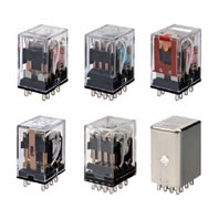
MY Miniature Power Relays
Ratings
Operating Coils
Terminal Type | Classification | Number of poles | Contacts | Without operation indicator | With operation indicator | ||||||||
Plug-in terminals | Standard models | 2 | Single | MY2 | MY2N | ||||||||
4 | Single | MY4 | MY4N | ||||||||||
Bifurcated | MY4Z | MY4ZN | |||||||||||
Models with built-in diode for coil surge absorption (DC coil specification only) | 2 | Single | MY2-D | MY2N-D2 | |||||||||
4 | Single | MY4-D | MY4N-D2 | ||||||||||
Bifurcated | MY4Z-D | MY4ZN-D2 | |||||||||||
Models with built-in CR circuit for coil surge absorption (AC coil specification only) | 2 | Single | MY2-CR | MY2N-CR | |||||||||
4 | Single | MY4-CR | MY4N-CR | ||||||||||
Bifurcated | MY4Z-CR | MY4ZN-CR | |||||||||||
Item | Rated current (mA) | Coil resistance (Ω) | Coil inductance (H) | Must operate voltage (V) | Must release voltage (V) | Maximum voltage (V) | Power consumption (VA, W) | ||||||
Rated voltage (V) | 50 Hz | 60 Hz | Armature OFF | Armature ON | |||||||||
AC | 12 | 106.5 | 91 | 46 | 0.17 | 0.33 | 80% max. *1 | 30% min. *2 | 110% of rated voltage | Approx. 0.9 to 1.3 (at 60 Hz) | |||
24 | 53.8 | 46 | 180 | 0.69 | 1.3 | ||||||||
100/110 | 11.7/12.9 | 10/11 | 3,750 | 14.54 | 24.6 | ||||||||
110/120 | 9.9/10.8 | 8.4/9.2 | 4,430 | 19.2 | 32.1 | ||||||||
200/220 | 6.2/6.8 | 5.3/5.8 | 12,950 | 54.75 | 94.07 | ||||||||
220/240 | 4.8/5.3 | 4.2/4.6 | 18,790 | 83.5 | 136.4 | ||||||||
DC | 12 | 72.7 | 165 | 0.73 | 1.37 | 10% min. *2 | Approx. 0.9 | ||||||
24 | 36.3 | 662 | 3.2 | 5.72 | |||||||||
48 | 17.6 | 2,725 | 10.6 | 21.0 | |||||||||
100/110 | 8.7/9.6 | 11,440 | 45.6 | 86.2 | |||||||||
Note: 1. The rated current and coil resistance are measured at a coil temperature of 23°C with tolerances of +15%/-20% for AC rated current and ±15% for DC coil resistance.
2. The AC coil resistance and inductance values are reference values only (at 60 Hz).
3. Operating characteristics were measured at a coil temperature of 23°C.
4. The maximum voltage capacity was measured at an ambient temperature of 23°C.
*1.There is variation between products, but actual values are 80% maximum.
To ensure operation, apply at least 80% of the rated value (at a coil temperature of 23°C).
*2.There is variation between products, but actual values are 30% minimum for AC and 10% minimum for DC.
To ensure release, use a value that is lower than the specified value.
Terminal Type | Classification | Number of poles | Contacts | Without operation indicator | With operation indicator | ||||||||
Plug-in terminals | Standard models | 2 | Bifurcated | MY2Z | MY2ZN | ||||||||
Models with built-in diode for coil surge absorption (DC coil specification only) | 2 | Bifurcated | MY2Z-D | MY2ZN-D2 | |||||||||
3 | Single | MY3-D | MY3N-D2 | ||||||||||
Models with built-in CR circuit for coil surge absorption (AC coil specification only) | 2 | Bifurcated | MY2Z-CR | MY2ZN-CR | |||||||||
Item | Rated current (mA) | Coil resistance (Ω) | Coil inductance (H) | Must operate voltage (V) | Must release voltage (V) | Maximum voltage (V) | Power consumption (VA, W) | ||||||
Rated voltage (V) | 50 Hz | 60 Hz | Armature OFF | Armature ON | |||||||||
AC | 12 | 106.5 | 91 | 46 | 0.17 | 0.33 | 80% max. *1 | 30% min. *2 | 110% of rated voltage | Approx. 0.9 to 1.3 (at 60 Hz) | |||
24 | 53.8 | 46 | 180 | 0.69 | 1.3 | ||||||||
100/110 | 11.7/12.9 | 10/11 | 3,750 | 14.54 | 24.6 | ||||||||
110/120 | 9.9/10.8 | 8.4/9.2 | 4,430 | 19.2 | 32.1 | ||||||||
200/220 | 6.2/6.8 | 5.3/5.8 | 12,950 | 54.75 | 94.07 | ||||||||
220/240 | 4.8/5.3 | 4.2/4.6 | 18,790 | 83.5 | 136.4 | ||||||||
DC | 12 | 75 | 160 | 0.73 | 1.37 | 10% min. *2 | Approx. 0.9 | ||||||
24 | 36.9 | 650 | 3.2 | 5.72 | |||||||||
48 | 18.5 | 2,600 | 10.6 | 21.0 | |||||||||
100/110 | 9.1/10 | 11,000 | 45.6 | 86.2 | |||||||||
Note: 1. The rated current and coil resistance are measured at a coil temperature of 23°C with tolerances of +15%/-20% for AC rated current and ±15% for DC coil resistance.
2. The AC coil resistance and inductance values are reference values only (at 60 Hz).
3. Operating characteristics were measured at a coil temperature of 23°C.
4. The maximum voltage capacity was measured at an ambient temperature of 23°C.
*1.There is variation between products, but actual values are 80% maximum.
To ensure operation, apply at least 80% of the rated value.
*2.There is variation between products, but actual values are 30% minimum for AC and 10% minimum for DC.
To ensure release, use a value that is lower than the specified value.
Terminal Type | Classification | Number of poles | Contacts | With latching lever | |||||||
Plug-in terminals | Standard models | 2 | Single | MY2IN(S) | |||||||
4 | Single | MY4IN(S) | |||||||||
Bifurcated | MY4ZIN(S) | ||||||||||
Models with built-in diode for coil surge absorption (DC coil specification only) | 2 | Single | MY2IN-D2(S) | ||||||||
4 | Single | MY4IN-D2(S) | |||||||||
Bifurcated | MY4ZIN-D2(S) | ||||||||||
Models with built-in CR circuit for coil surge absorption (AC coil specification only) | 2 | Single | MY4IN-CR(S) | ||||||||
4 | Bifurcated | MY4ZIN-CR(S) | |||||||||
Item | Rated current (mA) | Coil resistance (Ω) | Coil inductance (H) | Must operate voltage (V) | Must release voltage (V) | Maximum voltage (V) | Power consumption (VA, W) | ||||
Rated voltage (V) | 50 Hz | 60 Hz | Armature OFF | Armature ON | |||||||
AC | 100/110 | 11.7/12.9 | 10/11 | 3,750 | 14.54 | 24.6 | 80% max. *1 | 30% min. *2 | 110% of rated voltage | Approx. 0.9 to 1.3 (at 60 Hz) | |
200/220 | 6.2/6.8 | 5.3/5.8 | 12,950 | 54.75 | 94.07 | ||||||
DC | 12 | 75 | 160 | 0.73 | 1.37 | 10% min. *2 | Approx. 0.9 | ||||
24 | 37.7 | 636 | 3.2 | 5.72 | |||||||
48 | 18.8 | 2,560 | 10.6 | 21 | |||||||
Note: 1. The rated current and coil resistance are measured at a coil temperature of 23°C with tolerances of +15%/-20%
for AC rated current and ±15% for DC coil resistance.
2. The AC coil resistance and inductance values are reference values only (at 60 Hz).
3. Operating characteristics were measured at a coil temperature of 23°C.
4. The maximum voltage capacity was measured at an ambient temperature of 23°C.
*1.There is variation between products, but actual values are 80% maximum.
To ensure operation, apply at least 80% of the rated value.
*2.There is variation between products, but actual values are 30% minimum for AC and 10% minimum for DC.
To ensure release, use a value that is lower than the specified value.
Terminal Type | Classification | Number of poles | Contacts | Without operation indicator | With operation indicator | ||||||||
Plug-in terminals | Standard models | 3 | Single | MY3 | MY3N | ||||||||
4 | Crossbar bifurcated | MY4Z-CBG | MY4ZN-CBG | ||||||||||
PCB terminals | Standard models | 2 | Single | MY2-02 | — | ||||||||
3 | Single | MY3-02 | — | ||||||||||
4 | Single | MY4-02 | — | ||||||||||
Bifurcated | MY4Z-02 | — | |||||||||||
Case-surface mounting | Standard models | 2 | Single | MY2F | — | ||||||||
3 | Single | MY3F | — | ||||||||||
4 | Single | MY4F | — | ||||||||||
Bifurcated | MY4ZF | — | |||||||||||
Item | Rated current (mA) | Coil resistance (Ω) | Coil inductance (H) | Must operate voltage (V) | Must release voltage (V) | Maximum voltage (V) | Power consumption (VA, W) | ||||||
Rated voltage (V) | 50 Hz | 60 Hz | Armature OFF | Armature ON | |||||||||
AC | 12 | 106.5 | 91 | 46 | 0.17 | 0.33 | 80% max. *1 | 30% min. *2 | 110% of rated voltage | Approx. 0.9 to 1.3 (at 60 Hz) | |||
24 | 53.8 | 46 | 180 | 0.69 | 1.3 | ||||||||
100/110 | 11.7/12.9 | 10/11 | 3,750 | 14.54 | 24.6 | ||||||||
110/120 | 9.9/10.8 | 8.4/9.2 | 4,430 | 19.2 | 32.1 | ||||||||
200/220 | 6.2/6.8 | 5.3/5.8 | 12,950 | 54.75 | 94.07 | ||||||||
220/240 | 4.8/5.3 | 4.2/4.6 | 18,790 | 83.5 | 136.4 | ||||||||
DC | 12 | 75 | 160 | 0.73 | 1.37 | 10% min. *2 | Approx. 0.9 | ||||||
24 | 36.9 | 650 | 3.2 | 5.72 | |||||||||
48 | 18.5 | 2,600 | 10.6 | 21.0 | |||||||||
100/110 | 9.1/10 | 11,000 | 45.6 | 86.2 | |||||||||
Note: 1. The rated current and coil resistance are measured at a coil temperature of 23°C with tolerances of +15%/-20%
for AC rated current and ±15% for DC coil resistance.
2. The AC coil resistance and inductance values are reference values only (at 60 Hz).
3. Operating characteristics were measured at a coil temperature of 23°C.
4. The maximum voltage capacity was measured at an ambient temperature of 23°C.
*1.There is variation between products, but actual values are 80% maximum.
To ensure operation, apply at least 80% of the rated value.
*2.There is variation between products, but actual values are 30% minimum for AC and 10% minimum for DC. To ensure
release, use a value that is lower than the specified value.
Contact Ratings
Number of poles (contact configuration) | 2-pole (DPDT) | 3-pole (3PDT) | ||||||||||
Contact structure | Single | Bifurcated | Single | |||||||||
With latching lever (S) | ||||||||||||
Load | Resistive load | Inductive load (cos φ = 0.4, L/R = 7 ms) | Resistive load | Inductive load (cos φ = 0.4, L/R = 7 ms) | Resistive load | Inductive load (cos φ = 0.4, L/R = 7 ms) | Resistive load | Inductive load (cos φ = 0.4, L/R = 7 ms) | ||||
Rated load | 5 A at 220 VAC 5 A at 24 VDC | 2 A at 220 VAC 2 A at 24 VDC | 5 A at 250 VAC 5 A at 30 VDC | 2 A at 250 VAC 2 A at 30 VDC | 5 A at 220 VAC 5 A at 24 VDC | 2 A at 220 VAC 2 A at 24 VDC | 5 A at 220 VAC 5 A at 24 VDC | 2 A at 220 VAC 2 A at 24 VDC | ||||
Rated carry current*1 | 5 A (10 A*2) | 5 A | 5 A | |||||||||
Maximum switching voltage | 250 VAC, 125 VDC | 250 VAC, 125 VDC | ||||||||||
Maximum switching current | 5 A | 10 A | 5 A | 5 A | ||||||||
Maximum switching power | 1,100 VA 120 W | 440 VA 48 W | 2,500 VA 300 W | 500 VA 60 W | 1,100 VA 120 W | 440 VA 48 W | 1,100 VA 120 W | 440 VA 48 W | ||||
Contact material | Ag | Au plating + Ag | Ag | |||||||||
Number of poles (contact configuration) | 4-pole (4PDT) | |||||||||||
Contact structure | Single | |||||||||||
With latching lever (S) | ||||||||||||
Load | Resistive load | Inductive load (cos φ = 0.4, L/R = 7 ms) | Resistive load | Inductive load (cos φ = 0.4, L/R = 7 ms) | ||||||||
Rated load | 3 A at 220 VAC 3 A at 24 VDC | 0.8 A at 220 VAC 1.5 A at 24 VDC | 3 A at 250 VAC 3 A at 30 VDC | 0.8 A at 250 VAC 1.5 A at 30 VDC | ||||||||
Rated carry current*1 | 3 A (5 A*2) | |||||||||||
Maximum switching voltage | 250 VAC, 125 VDC | |||||||||||
Maximum switching current | 3 A (5 A*2) | |||||||||||
Maximum switching power | 660 VA 72 W | 176 VA 36 W | 1,250 VA 150 W | 200 VA 45 W | ||||||||
Contact material | Au cladding + Ag alloy (Au plating + Ag*3) | |||||||||||
Number of poles (contact configuration) | 4-pole (4PDT) | |||||
Contact structure | Bifurcated | Crossbar bifurcated (CBG) | ||||
With latching lever (S) | ||||||
Load | Resistive load | Inductive load (cos φ = 0.4, L/R = 7 ms) | Resistive load | Inductive load (cos φ = 0.4, L/R = 7 ms) | Resistive load | Inductive load (cos φ = 0.4, L/R = 7 ms) |
Rated load | 3 A at 220 VAC 3 A at 24 VDC | 0.8 A at 220 VAC 1.5 A at 24 VDC | 3 A at 250 VAC 3 A at 30 VDC | 0.8 A at 250 VAC 1.5 A at 30 VDC | 1 A at 220 VAC 1 A at 24 VDC | 0.3 A at 220 VAC 0.5 A at 24 VDC |
Rated carry current*1 | 3 A (5 A*2) | 1 A | ||||
Maximum switching voltage | 250 VAC, 125 VDC | |||||
Maximum switching current | 3 A (5 A*2) | 1 A | ||||
Maximum switching power | 660 VA 72 W | 176 VA 36 W | 1,250 VA 150 W | 200 VA 45 W | 220 VA 24 W | 66 VA 12 W |
Contact material | Au cladding + Ag alloy (Au plating + Ag*3) | Au cladding + AgPd | ||||
*1.If you use a Socket, do not exceed the rated carry current of the Socket.
*2.Values shown in parentheses are for the MY[](S) model with latching lever.
*3. For MY[]-02 relays with PCB terminals and MY[]F case-surface-mounting relays.
*2.Values shown in parentheses are for the MY[](S) model with latching lever.
*3. For MY[]-02 relays with PCB terminals and MY[]F case-surface-mounting relays.
Characteristics
Number of poles (contact configuration) | 2-pole (DPDT) | 3-pole (3PDT) | ||
Contact structure | Single | Bifurcated | Single | |
Contact resistance*1 *2 | 50 mΩ max. | |||
Operate time*3 | 20 ms max. | |||
Release time*3 | 20 ms max. | |||
Maximum switching frequency | Mechanical | 18,000 operations/h | ||
Rated load | 1,800 operations/h | |||
Insulation resistance*4*5 | 100 MΩ min. | |||
Dielectric strength | Between coil and contacts | 2,000 VAC, 50/60 Hz for 1 min | ||
Between contacts of different polarity | ||||
Between contacts of the same polarity | 1,000 VAC at 50/60 Hz for 1 min | |||
Vibration resistance | Destruction | 10 to 55 to 10 Hz, 0.5-mm single amplitude (1.0-mm double amplitude) | ||
Malfunction | 10 to 55 to 10 Hz, 0.5-mm single amplitude (1.0-mm double amplitude) | |||
Shock resistance | Destruction | 1,000 m/s2 | ||
Malfunction | 200 m/s2 | |||
Endurance | Mechanical | AC: 50,000,000 operations min. DC: 100,000,000 operations min. (switching frequency: 18,000 operations/h) | AC: 50,000,000 operations min. DC: 50,000,000 operations min. (switching frequency: 18,000 operations/h) | AC: 50,000,000 operations min. DC: 100,000,000 operations min. (switching frequency: 18,000 operations/h) |
Electrical*6 | 500,000 operations min. (rated load, switching frequency: 1,800 operations/h) | 200,000 operations min. (rated load, switching frequency: 1,800 operations/h) | 500,000 operations min. (rated load, switching frequency: 1,800 operations/h) | |
Failure rate P value (reference value)*7 | 1 mA at 5 VDC | 100 μA at 1 VDC | 1 mA at 5 VDC | |
Weight | Approx. 35 g | Approx. 35 g | Approx. 35 g | |
Number of poles (contact configuration) | 4-pole (4PDT) | |||
Contact structure | Single | Bifurcated | Crossbar bifurcated (CBG) | |
Contact resistance*1 *2 | 50 mΩ max. | 100 mΩ max. | ||
Operate time*3 | 20 ms max. | |||
Release time*3 | 20 ms max. | |||
Maximum switching frequency | Mechanical | 18,000 operations/h | ||
Rated load | 1,800 operations/h | |||
Insulation resistance*4*5 | 100 MΩ min. | |||
Dielectric strength | Between coil and contacts | 2,000 VAC, 50/60 Hz for 1 min | ||
Between contacts of different polarity | ||||
Between contacts of the same polarity | 1,000 VAC at 50/60 Hz for 1 min | 700 VAC at 50/60 Hz for 1 min | ||
Vibration resistance | Destruction | 10 to 55 to 10 Hz, 0.5-mm single amplitude (1.0-mm double amplitude) | ||
Malfunction | 10 to 55 to 10 Hz, 0.5-mm single amplitude (1.0-mm double amplitude) | |||
Shock resistance | Destruction | 1,000 m/s2 | ||
Malfunction | 200 m/s2 | |||
Endurance | Mechanical | AC: 50,000,000 operations min. DC: 100,000,000 operations min. (switching frequency: 18,000 operations/h) | AC: 20,000,000 operations min. DC: 20,000,000 operations min. (switching frequency: 18,000 operations/h) | AC: 5,000,000 operations min. DC: 5,000,000 operations min. (switching frequency: 18,000 operations/h) |
Electrical*6 | 200,000 operations min. (rated load, switching frequency: 1,800 operations/h) | 100,000 operations min. (rated load, switching frequency: 1,800 operations/h) | 50,000 operations min. (rated load, switching frequency: 1,800 operations/h) | |
Failure rate P value (reference value)*7 | 1 mA at 1 VDC | 100 μA at 1 VDC | 100 μA at 1 VDC | |
Weight | Approx. 35 g | Approx. 35 g | Approx. 35 g | |
Note: The data shown above are initial values.
*1. Models with latching lever are 100 mΩ maximum.
*2. Measurement conditions: 1 A at 5 VDC using the voltage drop method.
*3. Measurement conditions: With rated operating power applied, not including contact bounce.
*4. Measurement conditions: For 500 VDC applied to the same location as for dielectric strength measurement.
*5. Models with latching lever are 1,000 mΩ minimum.
*6. Ambient temperature condition: 23°C
*7. This value was measured at a switching frequency of 120 operations per minute.
Classification | Standard models | Models with built-in diode for coil surge absorption (-D)/ Models with built-in CR circuit for coil surge absorption (-CR) | ||||||
Contacts | Single/bifurcated | Crossbar/bifurcated (CBG) | Single/bifurcated | |||||
Features | Without operation indicator | With operation indicator | Without operation indicator | With operation indicator | Without operation indicator | With operation indicator | ||
With latching lever | With latching lever | |||||||
Ambient operating temperature *1 | -55 to 70°C | -55 to 60°C *2 | -55 to 70°C | -25 to 70°C | -25 to 60°C | -55 to 60°C *2 | -55 to 60°C *2 | -55 to 70°C |
Ambient operating humidity | 5% to 85% | 5% to 85% | ||||||
*1.With no icing or condensation.
*2.This limitation is due to the diode junction temperature and elements used.
*2.This limitation is due to the diode junction temperature and elements used.
Certified Standards
UL certification (File No. E41515)
Model | Standard number | Category | Listed/ Recognized | Operating Coil ratings | No. of poles | Contact ratings | Certified number of operations |
MY2 MY2N MY2IN(S) MY2-D MY2N-D2 MY2IN-D2(S) MY2-CR MY2N-CR | UL508 | NRNT2 | Recognition | 6 to 240 VAC 6 to 125 VDC | 2 | 10 A, 250 VAC (General Use) 10 A, 30 VDC (General Use) 7 A, 240 VAC (General Use) 7 A, 24 VDC (Resistive) 5 A, 240 VAC (General Use) 5 A, 250 VAC (Resistive) 5 A, 30 VDC (Resistive) 3 A, 265 VAC (Resistive) | 6,000 |
1/6 HP, 250 VAC 1/8 HP, 265 VAC 1/10 HP, 120 VAC | 1,000 | ||||||
B300 Pilot Duty (Same polarity) | 6,000 | ||||||
MY2Z MY2ZN MY2-02 MY2F MY2Z-D MY2ZN-D2 MY2Z-CR MY2ZN-CR | UL508 | NRNT2 | Recognition | 6 to 240 VAC 6 to 125 VDC | 2 | 7 A, 240 VAC (General Use) 7 A, 24 VDC (Resistive) 5 A, 240 VAC (General Use) 5 A, 250 VAC (Resistive) 5 A, 30 VDC (Resistive) 3 A, 265 VAC (Resistive) | 6,000 |
1/6 HP, 250 VAC 1/8 HP, 265 VAC 1/10 HP, 120 VAC | 1,000 | ||||||
B300 Pilot Duty (Same polarity) | 6,000 | ||||||
MY3 MY3N MY3-D MY3N-D2 MY3-02 MY3F | UL508 | NRNT2 | Recognition | 6 to 240 VAC 6 to 125 VDC | 3 | 5 A, 28 VDC (Resistive) 5 A, 240 VAC (General Use) | 6,000 |
1/6 HP, 250 VAC | 1,000 | ||||||
MY4 MY4N MY4IN(S) MY4-D MY4N-D2 MY4IN-D2(S) MY4Z MY4ZN MY4ZIN(S) MY4Z-D MY4ZN-D2 MY4ZIN-D2(S) MY4Z-CR MY4ZN-CR MY4ZIN-CR(S) MY4-02 MY4F MY4Z-02 MY4ZF | UL508 | NRNT2 | Recognition | 6 to 240 VAC 6 to 125 VDC | 4 | 5 A, 28 VDC (General Use) (Same polarity) 5 A, 240 VAC (General Use) (Same polarity) 5 A, 30 VDC (Resistive) (Same polarity) 5 A, 250 VAC (Resistive) (Same polarity) 0.2 A, 120 VDC (Resistive) (Same polarity) | 6,000 |
1/6 HP, 250 VAC (Same polarity) 1/10 HP, 120 VAC (Same polarity) | 1,000 | ||||||
B300 Pilot Duty (Same polarity) | 6,000 |
CSA certification (File No. LR31928)
Model | Standard number | Class number | Operating Coil ratings | No. of poles | Contact ratings | Certified number of operations |
MY2 MY2N MY2IN(S) MY2-D MY2N-D2 MY2IN-D2(S) MY2-CR MY2N-CR | C22.2 No.0, No.14 | 6 to 240 VAC 6 to 125 VDC | 2 | 7 A, 240 VAC (Resistive) 7 A, 24 VDC (Resistive) 5 A, 240 VAC (General Use) 5 A, 250 VAC (Resistive) 5 A, 30 VDC (Resistive) | 6,000 | |
1/6 HP, 250 VAC (Same polarity) 1/10 HP, 120 VAC (Same polarity) | 1,000 | |||||
MY2Z MY2ZN MY2-02 MY2F MY2Z-D MY2ZN-D2 MY2Z-CR MY2ZN-CR | C22.2 No.0, No.14 | 6 to 240 VAC 6 to 125 VDC | 2 | 7 A, 240 VAC (General Use) (Same polarity) 7 A, 24 VDC (Resistive) (Same polarity) 5 A, 240 VAC (General Use) (Same polarity) 5 A, 30 VDC (Resistive) 5 A, 250 VAC (Resistive) (Same polarity) 0.2 A, 120 VDC (Resistive) | 6,000 | |
1/6 HP, 250 VAC 1/10 HP, 120 VAC | 1,000 | |||||
MY3 MY3N MY3-D MY3N-D2 MY3-02 MY3F | C22.2 No.0, No.14 | 6 to 240 VAC 6 to 125 VDC | 3 | 5 A, 28 VDC (Resistive) 5 A, 240 VAC (General Use) 7 A, 240 VAC (General Use) 7 A, 24 VDC (Resistive) | 6,000 | |
1/6 HP, 250 VAC | 1,000 | |||||
MY4 MY4N MY4N(S) MY4-D MY4N-D2 MY4IN-D2(S) MY4-CR MY4N-CR MY4IN-CR(S) MY4Z MY4ZN MY4ZIN(S) MY4Z-D MY4ZN-D2 MY4ZIN-D2(S) MY4Z-C MY4ZN-CR MY4ZIN-CR(S) | C22.2 No.14 | 3211 07 | 6 to 240 VAC 6 to 125 VDC | 4 | 5 A, 240 VAC (General Use) (Same polarity) 5 A, 28 VDC (General Use) (Same polarity) 5 A, 250 VAC (Resistive) (Same polarity) 5 A, 30 VDC (Resistive) (Same polarity) 0.2 A, 120 VDC (Resistive) (Same polarity) | 6,000 |
1/6 HP, 250 VAC (Same polarity) 1/10 HP, 120 VAC (Same polarity) | 1,000 | |||||
B300 Pilot Duty (Same polarity) | 6,000 | |||||
MY4-02 MY4F MY4Z-02 MY4ZF | C22.2 No.0, No.14 | 3211 07 | 6 to 240 VAC 6 to 125 VDC | 4 | 7 A, 240 VAC (General Use) (Same polarity) 7 A, 24 VDC (Resistive) (Same polarity) 5 A, 240 VAC (General Use) (Same polarity) 5 A, 30 VDC (Resistive) 5 A, 250 VAC (Resistive) (Same polarity) 0.2 A, 120 VDC (Resistive) | 6,000 |
1/6 HP, 250 VAC 1/10 HP, 120 VAC | 1,000 |
TÜV Rheinland certification (Certification No. R50030059)
Model | Operating Coil ratings | Contact ratings | Certified number of operations |
MY2Z MY2ZN MY2-02 MY2F MY2Z-D MY2ZN-D2 MY2Z-CR MY2ZN-CR | 6 to 125 VDC, 6 to 240 VAC | 5 A, 250 VAC (cos φ = 1.0) | 100,000 |
MY3 MY3N MY3-D MY3N-D2 MY3-02 MY3F | 5 A, 250 VAC (cos φ = 1.0) 0.8 A, 250 VAC (cos φ = 0.4) | ||
MY4-02 MY4F MY4Z-02 MY4ZF | 3 A, 120 VAC (cos φ = 1.0) 0.8 A, 250 VAC (cos φ = 0.4) |
CE Marking
Model | EMC Directive | Low Voltage Directive | Machinery Directive | Safety Category |
MY2 MY2N MY2IN(S) MY2Z MY2ZN MY2-D MY2N-D2 MY2IN-D2(S) MY2-CR MY2N-CR MY2Z-CR MY2ZN-CR MY2Z-D MY2ZN-D2 MY2F | Not applicable | Applicable | Not applicable | 1 |
MY3 MY3N MY3-D MY3N-D2 MY3F | ||||
MY4 MY4N MY4IN(S) MY4Z MY4ZN MY4ZIN(S) MY4-D MY4N-D2 MY4IN-D2(S) MY4Z-D MY4ZN-D2 MY4ZIN-D2(S) MY4-CR MY4N-CR MY4Z-CR MY4ZN-CR MY4F MY4ZF |
LR certification (Lloyd’s Register)
Model | File No. | Environmental Category | Operating Coil ratings | Contact ratings | Certified number of operations |
MY2 MY2N MY2IN(S) MY2-D MY2N-D2 MY2IN-D2(S) MY2-CR MY2N-CR | File No.98/10014 | ENV2,3 | 6 to 240 VAC 6 to 125 VDC | 10 A, 250 VAC (Resistive) 2 A, 250 VAC (PF0.4) 10 A, 30 VDC (Resistive) 2 A, 30 VDC (L/R = 7 ms) | MY2: 50,000 |
MY2Z MY2ZN MY2Z-D MY2ZN-D2 | File No.90/10270 | ENV2,3 | 6 to 240 VAC 6 to 125 VDC | 2 A, 30 VDC inductive load 2 A, 200 VAC inductive load | MY2: 50,000 |
MY4 MY4N MY4IN(S) MY4-D MY4N-D2 MY4IN-D2(S) MY4-CR MY4N-CR MY4IN-CR(S) MY4Z MY4ZN MY4ZIN(S) MY4Z-D MY4ZN-D2 MY4ZIN-D2(S) MY4Z-CR MY4ZN-CR MY4ZIN-CR(S) | File No.98/10014 | ENV2,3 | 6 to 240 VAC 6 to 125 VDC | 5 A, 250 VAC (Resistive) 0.8 A, 250 VAC (PF0.4) 5 A, 30 VDC (Resistive) 1.5 A, 30 VDC (L/R = 7 ms) | MY4: 50,000 |
VDE certification
Model | Standard number | Certification No. | Operating Coil ratings | Contact ratings | Certified number of operations |
MY2 MY2N MY2IN(S) MY2-D MY2N-D2 MY2IN-D2(S) MY2-CR MY2N-CR | EN 61810-1 | 112467UG | 6, 12, 24, 48/50, 100/110, 110/120, 200/220, 220/240 VAC 6, 12, 24, 48, 100/110, 125 VDC | 10A, 250 VAC (cos φ = 1) 10A, 30 VDC (L/R = 0 ms) | MY2: 100,000 MY4: 100,000 MY4Z: 50,000 (AC) |
MY4 MY4N MY4IN(S) MY4Z MY4ZN MY4ZIN(S) MY4-D MY4N-D2 MY4IN-D2(S) MY4Z-D MY4ZN-D2 MY4ZIN-D2(S) MY4-CR MY4N-CR MY4IN-CR(S) MY4Z-CR MY4ZN-CR MY4ZIN-CR(S) | 6, 12, 24, 48/50, 100/110, 110/120, 200/220, 220/240 VAC 6, 12, 24, 48, 100/110, 125 VDC | 5 A, 250 VAC (cos φ = 1) 5 A, 30 VDC (L/R = 0 ms) |
MYK Miniature Power Latching Relays
Ratings
Operating coil
Rated voltage (V) | Set coil | Reset coil | Must operate voltage (V) | Must release voltage (V) | Maximum voltage (V) | Power consumption (VA, W) | ||||||
Rated current (mA) | Coil resistance (Ω) | Rated current (mA) | Coil resistance (Ω) | Set coil | Reset coil | |||||||
50 Hz | 60 Hz | 50 Hz | 60 Hz | |||||||||
AC | 12 | 57 | 56 | 72 | 39 | 38.2 | 130 | 80% max.* | 80% max. | 110% max. of rated voltage | Approx. 0.6 to 0.9 (at 60 Hz) | Approx. 0.2 to 0.5 (at 60 Hz) |
24 | 27.4 | 26.4 | 320 | 18.6 | 18.1 | 550 | ||||||
100 | 7.1 | 6.9 | 5,400 | 3.5 | 3.4 | 3,000 | ||||||
DC | 12 | 110 | 110 | 50 | 235 | Approx. 1.3 | Approx. 0.6 | |||||
24 | 52 | 470 | 25 | 940 | ||||||||
48 | 27 | 1,800 | 16 | 3,000 | ||||||||
Note: 1. The rated current for AC is the value measured with a DC ammeter in half-wave rectification.
2. The rated current and coil resistance are measured at a coil temperature of 23°C with tolerances of +15%/-20%
for AC rated current and ±15% for DC coil resistance.
3. The AC coil resistance is a reference value only.
4. Operating characteristics were measured at a coil temperature of 23°C.
5. The maximum voltage capacity was measured at an ambient temperature of 23°C.
*There is variation between products, but actual values are 80% maximum.
Contact Ratings
Number of poles (contact configuration) | 2-pole (DPDT) | |
Contact structure | Single | |
Load | Resistive load | Inductive load (cos φ = 0.4, L/R = 7 ms) |
Rated load | 3 A at 220 VAC 3 A at 24 VDC | 0.8 A at 220 VAC 1.5 A at 24 VDC |
Rated carry current | 3 A | |
Maximum switching voltage | 250 VAC, 125 VDC | |
Maximum switching current | 3 A | |
Maximum switching power | 660 VA 72 W | 176 VA 36 W |
Contact material | Au plating + Ag | |
Characteristics
Contact resistance*1 | 50 mΩ max. | |
Set | Operate time*2 | AC: 30 ms max., DC: 15 ms max. |
Minimum pulse width | AC: 60 ms, DC: 30 ms | |
Reset | Release time*2 | AC: 30 ms max., DC: 15 ms max. |
Minimum pulse width | AC: 60 ms, DC: 30 ms | |
Maximum switching frequency | Mechanical | 18,000 operations/h |
Rated load | 1,800 operations/h | |
Insulation resistance*3 | 100 MΩ min. | |
Dielectric strength | Between coil and contacts Between contacts of different polarity | 1,500 VAC at 50/60 Hz for 1 min |
Between contacts of the same polarity | 1,000 VAC at 50/60 Hz for 1 min | |
Between set/reset coils | ||
Vibration resistance | Destruction | 10 to 55 to 10 Hz, 0.5-mm single amplitude (1.0-mm double amplitude) |
Malfunction | 10 to 55 to 10 Hz, 0.5-mm single amplitude (1.0-mm double amplitude) | |
Shock resistance | Destruction | 1,000 m/s2 |
Malfunction | 200 m/s2 | |
Endurance | Mechanical | 100,000,000 operations min. (switching frequency: 18,000 operations/h) |
Electrical*4 | 200,000 operations min. (at rated load, switching frequency: 1,800 operations/h) | |
Failure rate P value (reference value)*5 | 1 mA at 1 VDC | |
Ambient operating temperature*6 | -55 to 60°C | |
Ambient operating humidity | 5% to 85% | |
Weight | Approx. 30 g | |
Note: The data shown above are initial values.
*1.Measurement conditions: 1 A at 5 VDC using the voltage drop method.
*2.Measurement conditions: With rated operating power applied, not including contact bounce.
*3.Measurement conditions: For 500 VDC applied to the same location as for dielectric strength measurement.
*4.Ambient temperature condition: 23°C
*5.This value was measured at a switching frequency of 120 operations per minute.
*6.With no icing or condensation.
MYQ/MYH Miniature Power Sealed Relays
Operating coil
Rated voltage (V) | Rated current (mA) | Coil resistance (Ω) | Coil inductance (H) | Must operate voltage (V)*1 | Must release voltage (V)*2 | Maximum voltage (V) | Power consumption (VA, W) | |||
50 Hz | 60 Hz | Armature OFF | Armature ON | |||||||
AC | 24 | 53.8 | 46 | 180 | 0.69 | 1.3 | 80% max. | 30% min. | 110% max. of rated voltage | Approx. 0.9 to 1.3 (at 60 Hz) |
100/110 | 11.7/12.9 | 10/11 | 3,750 | 14.54 | 24.6 | |||||
110/120 | 9.9/10.8 | 8.4/9.2 | 4,430 | 19.2 | 32.1 | |||||
200/220 | 6.2/6.8 | 5.3/5.8 | 12,950 | 54.75 | 91.07 | |||||
220/240 | 4.8/5.3 | 4.2/4.6 | 18,790 | 83.5 | 136.4 | |||||
DC | 12 | 75 | 165 | 0.734 | 1.37 | 10% min. | Approx. 0.9 | |||
24 | 36.9 | 650 | 3.2 | 5.72 | ||||||
48 | 18.5 | 2,600 | 10.6 | 21.0 | ||||||
100/110 | 9.1/10 | 11,000 | 45.6 | 86.0 | ||||||
Note: 1. The rated current and coil resistance are measured at a coil temperature of 23°C with tolerances of +15%/-20%
for AC rated current and ±15% for DC coil resistance.
2. The AC coil resistance and coil inductance values are for reference only.
3. Operating characteristics were measured at a coil temperature of 23°C.
4. The maximum voltage capacity was measured at an ambient temperature of 23°C.
*1.There is variation between products, but actual values are 80% maximum. To ensure operation, apply at least 80% of
the rated value.
*2.There is variation between products, but actual values are 30% minimum for AC and 10% minimum for DC. To ensure
release, use a value that is lower than the specified value.
Contact Ratings
Plastic Sealed Relays: MYQ
Number of poles (contact configuration) | 4-pole (4PDT) | |
Contact structure | Single/bifurcated | |
Load | Resistive load | Inductive load (cos φ = 0.4, L/R = 7 ms) |
Rated load | 1 A at 220 VAC 1 A at 24 VDC | 0.5 A at 220 VAC 0.5 A at 24 VDC |
Rated carry current | 1 A | |
Maximum switching voltage | 250 VAC 125 VDC | |
Maximum switching current | 1 A | |
Maximum switching power | 220 VA 24 W | 110 VA 12 W |
Contact material | Au plating + Ag | |
Hermetically Sealed Relays: MYH
Number of poles (contact configuration) | 4-pole (4PDT) | |||
Contact structure | Single | Bifurcated | ||
Load | Resistive load | Inductive load (cos φ = 0.4, L/R = 7 ms) | Resistive load | Inductive load (cos φ = 0.4, L/R = 7 ms) |
Rated load | 3 A at 110 VAC 3 A at 24 VDC | 0.8 A at 110 VAC 1.5 A at 24 VDC | 3 A at 110 VAC 3 A at 24 VDC | 0.8 A at 110 VAC 1.5 A at 24 VDC |
Rated carry current | 3 A | |||
Maximum switching voltage | 125 VAC 125 VDC | |||
Maximum switching current | 3 A | |||
Maximum switching power | 330 VA 72 W | 88 VA 36 W | 330 VA 72 W | 88 VA 36 W |
Contact material | Au plating + Ag | |||
Characteristics
Model | MYQ | MYH | |
Contact resistance*1 | 50 mΩ max. | ||
Operate time*2 | 20 ms max. | ||
Release time*2 | 20 ms max. | ||
Maximum switching frequency | Mechanical | 18,000 operations/h | |
Rated load | 1,800 operations/h | ||
Insulation resistance*3 | 100 MΩ min. | ||
Dielectric strength | Between coil and contacts | 1,500 VAC at 50/60 Hz for 1 min | 1,000 VAC at 50/60 Hz for 1 min |
Between contacts of different polarity | 1,500 VAC at 50/60 Hz for 1 min | 1,000 VAC at 50/60 Hz for 1 min | |
Between contacts of the same polarity | 1,000 VAC at 50/60 Hz for 1 min | 700 VAC at 50/60 Hz for 1 min | |
Vibration resistance | Destruction | 10 to 55 to 10 Hz, 0.5-mm single amplitude (1.0-mm double amplitude) | |
Malfunction | 10 to 55 to 10 Hz, 0.5-mm single amplitude (1.0-mm double amplitude) | ||
Shock resistance | Destruction | 1,000 m/s2 | |
Malfunction | 200 m/s2 | ||
Endurance | Mechanical | Single contacts: AC: 50,000,000 operations min., DC: 100,000,000 operations min. Bifurcated contacts: 5,000,000 operations min., DC: 5,000,000 operations min. (switching frequency: 18,000 operations/h) | Single contacts: 50,000,000 operations min. Bifurcated contacts: 5,000,000 operations min. (switching frequency: 18,000 operations/h) |
Electrical*4 | Single contacts: 200,000 operations min. Bifurcated contacts: 100,000 operations min. (at rated load, switching frequency: 1,800 operations/h) | Single contacts: 100,000 operations min. Bifurcated contacts: 50,000 operations min. (at rated load, switching frequency: 1,800 operations/h) | |
Failure rate P Level (reference value)*5 | Single contacts: 1 mA at 1 VDC Bifurcated contacts: 100 μA at 1 VDC | Single contacts: 100 μA at 1 VDC Bifurcated contacts: 100 μA at 100 mVDC | |
Ambient operating temperature*6 | -55 to 60°C | -25 to 60°C | |
Ambient operating humidity | 5% to 85% | ||
Weight | Approx. 35 g | Approx. 50 g | |
Note: The data shown above are initial values.
*1.Measurement conditions: 1 A at 5 VDC using the voltage drop method.
*2.Measurement conditions: With rated operating power applied, not including contact bounce.
Ambient temperature condition:23°C
*3.Measurement conditions: For 500 VDC applied to the same location as for dielectric strength measurement.
*4.Ambient temperature condition:23°C
*5.This value was measured at a switching frequency of 120 operations per minute.
*6.With no icing or condensation.
Common Options (Order Separately)
Characteristics
Sockets

Socket Accessories
For Front-connecting Sockets
Short Bars
Application | Applicable sockets | Model | Maximum carry current | Ambient operating temperature | Ambient operating humidity |
Bridging contact terminals (common) | PYF-08-PU(-L) PYF-14-PU(-L) | PYDN-7.75-020[] | 20 A | -40 to 70°C | 5% to 85% |
PYDN-7.75-030[] | |||||
PYDN-7.75-040[] | |||||
PYDN-7.75-200[] | |||||
PYFZ-08 | PYD-025B[] | 20 A (However, 18 A when 70°C) | -40 to 70°C (with no icing or condensation) | 45% to 85% (with no icing or condensation) | |
PYD-085B[] | |||||
PYFZ-14 | PYD-026B[] | ||||
PYD-086B[] | |||||
PYD-020B[] | |||||
PYD-030B[] | |||||
For Coil terminals | PYF-08-PU(-L) PYF-14-PU(-L) | PYDN-31.0-080[] | 20 A | -40 to 70°C | 5% to 85% |
PYF08S | PYDM-08S[] | 10 A | -40 to 70°C | 5% to 85% | |
PYF14S | PYDM-14S[] | 10 A | -40 to 70°C | 5% to 85% |
Certified Standards
CSA certification (File No. LR031928)
Model | Ratings | Class number | Standard number |
PYF-08-PU | 10 A, 250 V | 3211 07 | CSA C22.2 No14 |
PYF-14-PU | 6 A, 250 V* | ||
PYF08S | 10 A, 250 V | ||
PYF14S | 5 A, 250 V | ||
PYFZ-08(-E) | 10 A, 250 V | ||
PYFZ-14(-E) | 6 A, 250 V | ||
PY[] PYF[]A | 7 A, 250 V |
* When power is supplied to all four poles, use with a total power current that does not exceed 20 A.
UL certification (File No. E87929)
Model | Ratings | Standard number | Category | Listed/Recognized |
PYF-08-PU | 10 A, 250 V | UL508 | SWIV2 | Recognition |
PYF-14-PU | 6 A, 250 V* | |||
PYF08S PYF14S | 10 A, 250 V | |||
PYFZ-08(-E) | 10 A, 250 V | |||
PYFZ-14(-E) | 6 A, 250 V | |||
PY[] PYF[]A | 7 A, 250 V |
* When power is supplied to all four poles, use with a total power current that does not exceed 20 A.
TÜV Rheinland certification
Model | Ratings | Standard number | Certification No. |
PYF-08-PU | 10 A, 250 V* | EN 61984 | R50327595 |
PYF-14-PU | 6 A, 250 V | ||
PYFZ-08(-E) | 10 A, 250 V | R50405329 | |
PYFZ-14(-E) | 6 A, 250 V |
*Ratings are for an ambient temperature of 55°C or below. At an ambient temperature of 70°C, the value is 7 A.
VDE certification
Model | Standard number | Certification No. |
PYF08S | VDE0627 (EN61984) | 40015509 |
PYF14 |