


 Build a simple and flexible safety system
Regulations and Standards
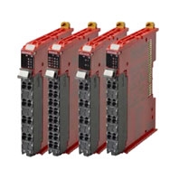
Safety I/O Units NX-SI/SO
Certification body | Standards |
TÜV Rheinland *1 | • EN ISO 13849-1 • EN ISO 13849-2 • IEC 61508 parts 1-7 • IEC/EN 62061 • IEC/EN 61131-2 • IEC 61326-3-1 |
UL | • NRAG (UL 508 and ANSI/ISA 12.12.01) • NRAG7 (CSA C22.2 No. 142 and CSA C22.2 No. 213) |
Shipbuilding Standards | NK, LK |
*1 Using the NX-series Safety I/O Units in conjunction with the NX-series Safety CPU Unit allows you to build a safety control
system that meets the following standards:
• Requirements for SIL 3 in IEC 61508 and IEC/EN 62061
• Requirements for PLe and Safety Category 4 in EN ISO 13849-1
The NX-series Safety I/O Units are also registered for RCM, EAC, and KC compliance.
system that meets the following standards:
• Requirements for SIL 3 in IEC 61508 and IEC/EN 62061
• Requirements for PLe and Safety Category 4 in EN ISO 13849-1
The NX-series Safety I/O Units are also registered for RCM, EAC, and KC compliance.
General Specifications
Item | Specification | |
Enclosure | Mounted in a panel (open) | |
Grounding method | Ground to 100 Ω or less. | |
Operating environment | Ambient operating temperature | 0 to 55°C (The upper limit of the ambient operating temperature is restricted by the installation orientation.) |
Ambient operating humidity | 10% to 95% (with no condensation or icing) | |
Atmosphere | Must be free from corrosive gases. | |
Ambient storage temperature | -25 to 70°C (with no condensation or icing) | |
Altitude | 2,000 m max. | |
Pollution degree | 2 or less. | |
Noise immunity | Conforms to IEC 61131-2. 2 kV on power supply line (Conforms to IEC 61000-4-4.) | |
Insulation class | Class III (SELV) | |
Overvoltage category | II | |
EMC immunity level | Zone B | |
Vibration resistance | Conforms to IEC 60068-2-6. 5 to 8.4 Hz with 3.5-mm amplitude, 8.4 to 150 Hz, acceleration of 9.8 m/s2, 100 minutes each in X, Y, and Z directions (10 sweeps of 10 min each = 100 min total) | |
Shock resistance | Conforms to IEC 60068-2-27. 147 m/s2, 3 times each in X, Y, and Z directions | |
Insulation resistance | 20 MΩ between isolated circuits (at 100 VDC) | |
Dielectric strength | 510 VAC for 1 min between isolated circuits, leakage current: 5 mA max. | |
Installation method | DIN Track (IEC 60715 TH35-7.5/TH35-15) | |
Unit Specifications
Safety Input Units NX-SIH400/SID800
Unit name | Safety Input Unit | |
Model | NX-SIH400 | NX-SID800 |
Number of safety input points | 4 points | 8 points |
Number of test output points | 2 points | 2 points |
Internal I/O common | PNP (sinking inputs) | |
Rated input voltage | 24 VDC (20.4 to 28.8 VDC) | |
OMRON special safety input devices | Can be connected. | Cannot be connected. |
Number of safety slave connections | 1 | |
I/O refreshing method | Free-Run refreshing | |
External connection terminals | Screwless clamping terminal block (8 terminals) | Screwless clamping terminal block (16 terminals) |
Indicators |  |  |
Safety input current | 4.5 mA typical | 3.0 mA typical |
Safety input ON voltage | 11 VDC min. | 15 VDC min. |
Safety input OFF voltage/OFF current | 5 VDC max., 1 mA max. | |
Test output type | Sourcing outputs (PNP) | |
Test output load current | 25 mA max. | 50 mA max. |
Test output residual voltage | 1.2 V max. (Between IOV and all output terminals) | |
Test output leakage current | 0.1 mA max. | |
Dimensions | 12 × 100 × 71 mm (W × H × D) | |
Isolation method | Photocoupler isolation | |
Insulation resistance | 20 MΩ min. between isolated circuits (at 100 VDC) | |
Dielectric strength | 510 VAC for 1 min between isolated circuits, leakage current: 5 mA max. | |
I/O power supply method | Power supplied from the NX bus | |
Current capacity of I/O power supply terminals | No applicable terminals. | |
NX Unit power consumption | • Connected to a CPU Unit or a Communication Control Unit *1 1.10 W max. • Connected to a Communications Coupler Unit *2 0.70 W max. | • Connected to a CPU Unit or a Communication Control Unit *1 1.10 W max. • Connected to a Communications Coupler Unit *2 0.75 W max. |
Current consumption from I/O power supply | 20 mA max. | |
Weight | 70 g max. | |
Circuit layout |  |  |
Terminal connection diagram | Si0 to Si3: Safety input terminals T0 and T1: Test output terminals  Refer to User's manual (Cat.No.Z930) for details. | Si0 to Si7: Safety input terminals T0 and T1: Test output terminals  Refer to User's manual (Cat.No.Z930) for details. |
Installation orientation and restrictions | Installation orientation: • Connected to a CPU Unit or a Communication Control Unit *1 Possible in the upright installation orientation. • Connected to a Communications Coupler Unit *2 6 possible orientations. Restrictions: Maximum ambient temperature is 50ºC for any orientation other than upright installation. | |
Protective functions | Overvoltage protection circuit and short detection (test outputs) | |
*1 It can be connected to the NX102 CPU unit or communication control unit. It cannot be connected to the NX1P2 CPU unit.
*2 The NX-ECC20 EtherCAT Coupler Unit and NX-EIC202 EtherNet/IP Coupler Unit can be connected.
*2 The NX-ECC20 EtherCAT Coupler Unit and NX-EIC202 EtherNet/IP Coupler Unit can be connected.
Safety Output Units NX-SOH200/SOD400
Unit name | Safety Output Unit | |
Model | NX-SOH200 | NX-SOD400 |
Number of safety output points | 2 points | 4 points |
Internal I/O common | PNP (sourcing outputs) | |
Maximum load current | 2.0 A/point 4.0 A/Unit at 40°C 2.5 A/Unit at 55°C The maximum load current depends on the installation orientation and ambient temperature. See Installation orientation and restrictions. | 0.5 A/point and 2.0 A/Unit |
Rated voltage | 24 VDC (20.4 to 28.8 VDC) | |
Number of safety slave connections | 1 | |
I/O refreshing method | Free-Run refreshing | |
External connection terminals | Screwless clamping terminal block (8 terminals) | |
Indicators |  |  |
Safety output ON residual voltage | 1.2 V max. (Between IOV and all output terminals) | |
Safety output OFF residual voltage | 2 V max. (Between IOG and all output terminals) | |
Safety output leakage current | 0.1 mA max. | |
Dimensions | 12 × 100 × 71 mm (W × H × D) | |
Isolation method | Photocoupler isolation | |
Insulation resistance | 20 MΩ min. between isolated circuits (at 100 VDC) | |
Dielectric strength | 510 VAC for 1 min between isolated circuits, leakage current: 5 mA max. | |
I/O power supply method | Power supplied from the NX bus | |
Current capacity of I/O power supply terminals | IOG: 2 A max./terminal | IOG (A3 and B3): 2 A max./terminal IOG (A7 and B7): 0.5 A max./terminal |
NX Unit power consumption | • Connected to a CPU Unit or a Communication Control Unit *1 1.05 W max. • Connected to a Communications Coupler Unit *2 0.70 W max. | • Connected to a CPU Unit or a Communication Control Unit *1 1.10 W max. • Connected to a Communications Coupler Unit *2 0.75 W max. |
Current consumption from I/O power supply | 40 mA max. | 60 mA max. |
Weight | 65 g max. | |
Circuit layout |  |  |
Terminal connection diagram | So0 and So1: Safety output terminals IOG: I/O power supply 0 V  Refer to User's manual (Cat.No.Z930) for details. | So0 to So3: Safety output terminals IOG: I/O power supply 0 V  Refer to User's manual (Cat.No.Z930) for details. |
Installation orientation and restrictions | Installation orientation: • Connected to a CPU Unit or a Communication Control Unit *1 Possible in the upright installation orientation. • Connected to a Communications Coupler Unit *2 6 possible orientations Restrictions: For upright installation, the ambient temperature is restricted as shown below depending on the total Unit load current.  For all installation orientations other than upright installation, the ambient temperature is restricted as shown below according to the total Unit load current.  | Installation orientation: • Connected to a CPU Unit or a Communication Control Unit *1 Possible in the upright installation orientation. • Connected to a Communications Coupler Unit *2 6 possible orientations Restrictions: None |
Protective functions | Overvoltage protection circuit and short detection | |
*1 The NX102 CPU Unit and the NX-CSG Communication Control Unit can be connected. The NX1P2 CPU Unit cannot be connected.
*2 The NX-ECC20 EtherCAT Coupler Unit and NX-EIC202 EtherNet/IP Coupler Unit can be connected.
*2 The NX-ECC20 EtherCAT Coupler Unit and NX-EIC202 EtherNet/IP Coupler Unit can be connected.
Version Information
The following table shows the possible combinations of versions of NX-series Safety I/O Units, CPU Units, Communications Coupler Units, Communication Control Unit, and Sysmac Studio. Available functions that are related to safety control vary depending on the versions of the units and Sysmac Studio. Refer to the NX-series Safety Control Unit User's Manual (Cat. No. Z930) for details.
Safety Control Unit model and version | NX bus master: CPU Unit | NX bus master: EtherCAT Coupler Unit | NX bus master: EtherNet/IP Coupler Unit | NX bus master: Communication Control Unit | ||||||
Model | Unit version | NX102 CPU unit | Sysmac Studio | Commu- nications Coupler Unit NX- ECC20[] | NJ/NX1P/ NX7 CPU Unit *1 | Sysmac Studio | Commu- nications Coupler Unit NX- EIC202 | Sysmac Studio | Commu- nications Control Unit NX-CSG | Sysmac Studio |
NX-SIH400 | Ver.1.0 | Ver.1.30 or later | Ver.1.22 or higher | Ver.1.2 or later | Ver.1.06 or later | Ver.1.07 or higher | --- | --- | Ver.1.00 or later | Ver.1.24 or higher |
Ver.1.1 | Ver.1.10 or higher | Ver.1.0 or later | Ver.1.10 or higher | Ver.1.24 or higher | ||||||
NX-SID800 | Ver.1.0 | Ver.1.30 or later | Ver.1.22 or higher | Ver.1.1 or later | Ver.1.06 or later | Ver.1.07 or higher | Ver.1.0 or later | Ver.1.10 or higher | Ver.1.00 or later | Ver.1.24 or higher |
NX-SOH200 | Ver.1.0 | Ver.1.30 or later | Ver.1.22 or higher | Ver.1.1 or later | Ver.1.06 or later | Ver.1.07 or higher | Ver.1.0 or later | Ver.1.10 or higher | Ver.1.00 or later | Ver.1.24 or higher |
NX-SOD400 | Ver.1.0 | Ver.1.30 or later | Ver.1.22 or higher | Ver.1.1 or later | Ver.1.06 or later | Ver.1.07 or higher | Ver.1.0 or later | Ver.1.10 or higher | Ver.1.00 or later | Ver.1.24 or higher |
*1 This is version information when the NJ/NX1P/NX7 CPU Unit is used as the EtherCAT master in the system. The Safety Control Unit cannot be connected directly to these CPU Units.