


Two-circuit Limit Switch
WL-N / WLG
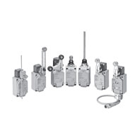 Two-circuit limit switches that can be selected to match the operating environment and application WL-N/Basic models, WLG/High-sensitivity and High-precision models
General-purpose Switches
Ratings
Screw terminals
Without Operation Indicator
Basic models (WL-N)
|
Ratings |
Non-inductive load (A) |
Inductive load (A) |
|||||||
|
Basic models (WL-N) |
Basic models (WL-N) |
||||||||
|
Resistive load |
Lamp load |
Inductive load |
Motor load |
||||||
|
Voltage (V) |
NC |
NO |
NC |
NO |
NC |
NO |
NC |
NO |
|
|
AC |
125 |
10 |
3 |
1.5 |
10 |
5 |
2.5 |
||
|
250 |
10 |
2 |
1 |
10 |
3 |
1.5 |
|||
|
500 |
10 |
1.5 |
0.8 |
3 |
1.5 |
0.8 |
|||
|
DC |
8 |
10 |
6 |
3 |
10 |
6 |
|||
|
14 |
10 |
6 |
3 |
10 |
6 |
||||
|
30 |
6 |
4 |
3 |
6 |
4 |
||||
|
125 |
0.8 |
0.2 |
0.2 |
0.8 |
0.2 |
||||
|
250 |
0.4 |
0.1 |
0.1 |
0.4 |
0.1 |
||||
High-sensitivity and High-precision models (WLG)
|
Ratings |
Non-inductive load (A) |
||
|
High-sensitivity and High-precision models (WLG) |
|||
|
Resistive load |
|||
|
Voltage (V) |
NC |
NO |
|
|
AC |
125 |
5 |
|
|
250 |
5 |
||
|
DC |
125 |
0.4 |
|
|
250 |
0.2 |
||
With Operation Indicator (LED)
Basic models (WL-N)
|
Ratings |
Non-inductive load (A) |
Inductive load (A) |
|||||||
|
Basic models (WL-N) |
Basic models (WL-N) |
||||||||
|
Resistive load |
Lamp load |
Inductive load |
Motor load |
||||||
|
Voltage (V) |
NC |
NO |
NC |
NO |
NC |
NO |
NC |
NO |
|
|
AC |
115 |
10 |
3 |
1.5 |
10 |
5 |
2.5 |
||
|
DC |
12 |
10 |
6 |
3 |
10 |
6 |
|||
|
24 |
6 |
4 |
3 |
6 |
4 |
||||
|
48 |
3 |
2 |
1.5 |
3 |
0.2 |
||||
|
115 |
0.8 |
0.2 |
0.8 |
0.1 |
|||||
High-sensitivity and High-precision models (WLG)
|
Ratings |
Non-inductive load (A) |
||
|
High-sensitivity and High-precision models (WLG) |
|||
|
Resistive load |
|||
|
Voltage (V) |
NC |
NO |
|
|
AC |
115 |
5 |
|
|
DC |
115 |
0.4 |
|
With Operation Indicators (Neon Lamps)
Basic models (WL-N)
|
Ratings |
Non-inductive load (A) |
Inductive load (A) |
|||||||
|
Basic models (WL-N) |
Basic models (WL-N) |
||||||||
|
Resistive load |
Lamp load |
Inductive load |
Motor load |
||||||
|
Voltage (V) |
NC |
NO |
NC |
NO |
NC |
NO |
NC |
NO |
|
|
AC |
125 |
10 |
3 |
1.5 |
10 |
5 |
2.5 |
||
|
250 |
10 |
2 |
1 |
10 |
3 |
1.5 |
|||
High-sensitivity and High-precision models (WLG)
|
Ratings |
Non-inductive load (A) |
||
|
High-sensitivity and High-precision models (WLG) |
|||
|
Resistive load |
|||
|
Voltage (V) |
NC |
NO |
|
|
AC |
125 |
5 |
|
|
250 |
5 |
||
Note: 1. The above figures are for steady-state currents.
2. Inductive loads have a power factor of 0.4 min. (AC) and a time constant of 7 ms max. (DC).
3. A lamp load has an inrush current of 10 times the steady-state current.
4. A motor load has an inrush current of 6 times the steady-state current.
Allowable Inrush Current/Minimum Applicable Load
|
Operating characteristics type |
Basic models (WL-N) |
High-sensitivity and |
|
|
Inrush current |
NC |
30 A max. |
15 A max. |
|
NO |
20 A max. |
10 A max. |
|
|
Minimum applicable load |
5 VDC 1 mA, resistive load, P level |
5 VDC 1 mA, resistive load, P level |
|
Operation Indicator
|
Operation indicator type |
LED |
Neon lamp |
|
Rated voltage |
10 to 115 VAC/DC |
125 to 250 VAC |
|
Leakage current |
Approx. 0.4 mA at 10 VAC/DC |
Approx. 0.6 mA at 125 VAC |
Direct-wired connector and Pre-wired Connector Type
Connector DC Specifications: With Operation Indicators (LEDs)
Basic models (WL-N)
|
Ratings |
Non-inductive load (A) |
Inductive load (A) |
|||||||
|
Basic models (WL-N) |
Basic models (WL-N) |
||||||||
|
Resistive load |
Lamp load |
Inductive load |
Motor load |
||||||
|
Voltage (V) |
NC |
NO |
NC |
NO |
NC |
NO |
NC |
NO |
|
|
DC |
12 |
3 |
3 |
3 |
3 |
||||
|
24 |
3 |
3 |
3 |
3 |
|||||
|
48 |
4 |
2 |
1.5 |
3 |
2 |
||||
|
115 |
0.8 |
0.2 |
0.2 |
0.8 |
0.2 |
||||
High-sensitivity and High-precision models (WLG)
|
Ratings |
Non-inductive load (A) |
||
|
High-sensitivity and High-precision models (WLG) |
|||
|
Resistive load |
|||
|
Voltage (V) |
NC |
NO |
|
|
DC |
115 |
0.4 |
|
Connector AC Specifications: With Operation Indicators (LEDs)
Basic models (WL-N)
|
Ratings |
Non-inductive load (A) |
Inductive load (A) |
|||||||
|
Basic models (WL-N) |
Basic models (WL-N) |
||||||||
|
Resistive load |
Lamp load |
Inductive load |
Motor load |
||||||
|
Voltage (V) |
NC |
NO |
NC |
NO |
NC |
NO |
NC |
NO |
|
|
AC |
115 |
3 |
3 |
1.5 |
3 |
3 |
2.5 |
||
High-sensitivity and High-precision models (WLG)
|
Ratings |
Non-inductive load (A) |
||
|
High-sensitivity and High-precision models (WLG) |
|||
|
Resistive load |
|||
|
Voltage (V) |
NC |
NO |
|
|
AC |
115 |
3 |
|
Note: 1. The above figures are for steady-state currents.
2. Inductive loads have a power factor of 0.4 min. (AC) and a time constant of 7 ms max. (DC).
3. A lamp load has an inrush current of 10 times the steady-state current.
4. A motor load has an inrush current of 6 times the steady-state current.
Minimum Applicable Load
|
Operating characteristics type |
Basic models (WL-N) |
High-sensitivity and |
|
Minimum applicable load |
5 VDC 1 mA, resistive load, P level |
5 VDC 1 mA, resistive load, P level |
Operation Indicator
|
Operation indicator type |
LED |
Neon lamp |
|
Rated voltage |
10 to 115 VAC/DC |
125 to 250 VAC |
|
Leakage current |
Approx. 0.4 mA at 10 VAC/DC |
Approx. 0.6 mA at 125 VAC |
Characteristics
|
Operating characteristics type |
Basic models (WL-N) |
High-sensitivity and |
|
|
Permissible operating |
Mechanical |
120 operations/minute |
|
|
Electrical |
30 operations/minute |
||
|
Rated frequency |
50/60 Hz |
||
|
Permissible operating speed |
1 mm/s to 1 m/s (in case of WLCA2-N) |
||
|
Insulation resistance |
100 MΩ min. (at 500 VDC) |
||
|
Contact resistance |
25 mΩ max. (initial value for the built-in switch) |
||
|
Vibration resistance |
Malfunction |
10 to 55 Hz, 1.5-mm double amplitude |
|
|
Shock |
Destruction |
1,000 m/s2 max. |
|
|
Malfunction |
300 m/s2 max. *2 |
||
|
Durability *1 |
Mechanical |
15,000,000 operations min. |
10,000,000 operations min. *4 |
|
Electrical |
750,000 operations min. (3 A at 250 |
500,000 operations min. (3 A at 250 |
|
|
Ambient operating temperature |
-10 to +80°C (with no icing) |
||
|
Ambient operating humidity |
35 to 95%RH |
||
|
Degree of protection |
IP67 |
||
|
Weight |
Approx. 255 g (in case of WLCA2-N) |
Approx. 270 g (in case of WLGCA2) |
|
Note: The above figures are initial values.
1. The values are calculated at an operating temperature of +5°C to +35°C, and an operating humidity of 40% to 70%RH. Contact your OMRON sales representative for more detailed information on other operating environments.
2. Except Switches with Flexible Rod Actuators.
3. In case of Screw terminals without operation indicators.
4. 15,000,000 operations min. for horizontal plunger models.
|
Operating characteristics type |
Basic models (WL-N) |
High-sensitivity and |
|||
|
Wiring Specifications |
Screw |
Direct-wire connector/ |
Screw |
Direct-wire connector/ |
|
|
Dielectric |
Between terminals |
1,000 VAC, |
600 VAC, |
600 VAC, |
600 VAC, |
|
Between current- |
2,200 VAC, |
1,500 VAC, |
1,500 VAC, |
1,500 VAC, |
|
|
Between each |
2,200 VAC, |
1,500 VAC, |
1,500 VAC, |
1,500 VAC, |
|
* Excluding those with operation indicators.
Environment-resistant Limit Switches
Ratings
Screw terminals/Direct-wire cable
Without Operation Indicator
Basic models (WL-N)
|
Ratings |
Non-inductive load (A) |
Inductive load (A) |
|||||||
|
Basic models (WL-N) |
Basic models (WL-N) |
||||||||
|
Resistive load |
Lamp load |
Inductive load |
Motor load |
||||||
|
Voltage (V) |
NC |
NO |
NC |
NO |
NC |
NO |
NC |
NO |
|
|
AC |
125 |
10 |
3 |
1.5 |
10 |
5 |
2.5 |
||
|
250 |
10 |
2 |
1 |
10 |
3 |
1.5 |
|||
|
500 |
10 |
1.5 |
0.8 |
3 |
1.5 |
0.8 |
|||
|
DC |
8 |
10 |
6 |
3 |
10 |
6 |
|||
|
14 |
10 |
6 |
3 |
10 |
6 |
||||
|
30 |
6 |
4 |
3 |
6 |
4 |
||||
|
125 |
0.8 |
0.2 |
0.2 |
0.8 |
0.2 |
||||
|
250 |
0.4 |
0.1 |
0.1 |
0.4 |
0.1 |
||||
High-sensitivity and High-precision models (WLG)
|
Ratings |
Non-inductive load (A) |
||
|
High-sensitivity and High-precision models (WLG) |
|||
|
Resistive load |
|||
|
Voltage (V) |
NC |
NO |
|
|
AC |
125 |
5 |
|
|
250 |
5 |
||
|
DC |
125 |
0.4 |
|
|
250 |
0.2 |
||
With Operation Indicator (LED)
Basic models (WL-N)
|
Ratings |
Non-inductive load (A) |
Inductive load (A) |
|||||||
|
Basic models (WL-N) |
Basic models (WL-N) |
||||||||
|
Resistive load |
Lamp load |
Inductive load |
Motor load |
||||||
|
Voltage (V) |
NC |
NO |
NC |
NO |
NC |
NO |
NC |
NO |
|
|
AC |
115 |
10 |
3 |
1.5 |
10 |
5 |
2.5 |
||
|
DC |
12 |
10 |
6 |
3 |
10 |
6 |
|||
|
24 |
6 |
4 |
3 |
6 |
4 |
||||
|
48 |
3 |
2 |
1.5 |
3 |
0.2 |
||||
|
115 |
0.8 |
0.2 |
0.8 |
0.1 |
|||||
High-sensitivity and High-precision models (WLG)
|
Ratings |
Non-inductive load (A) |
||
|
High-sensitivity and High-precision models (WLG) |
|||
|
Resistive load |
|||
|
Voltage (V) |
NC |
NO |
|
|
AC |
115 |
5 |
|
|
DC |
115 |
0.4 |
|
With Operation Indicators (Neon Lamps)
Basic models (WL-N)
|
Ratings |
Non-inductive load (A) |
Inductive load (A) |
|||||||
|
Basic models (WL-N) |
Basic models (WL-N) |
||||||||
|
Resistive load |
Lamp load |
Inductive load |
Motor load |
||||||
|
Voltage (V) |
NC |
NO |
NC |
NO |
NC |
NO |
NC |
NO |
|
|
AC |
125 |
10 |
3 |
1.5 |
10 |
5 |
2.5 |
||
|
250 |
10 |
2 |
1 |
10 |
3 |
1.5 |
|||
High-sensitivity and High-precision models (WLG)
|
Ratings |
Non-inductive load (A) |
||
|
High-sensitivity and High-precision models (WLG) |
|||
|
Resistive load |
|||
|
Voltage (V) |
NC |
NO |
|
|
AC |
125 |
5 |
|
|
250 |
5 |
||
Note: 1. The above figures are for steady-state currents.
2. Inductive loads have a power factor of 0.4 min. (AC) and a time constant of 7 ms max. (DC).
3. A lamp load has an inrush current of 10 times the steady-state current.
4. A motor load has an inrush current of 6 times the steady-state current.
Allowable Inrush Current/ Minimum applicable load
|
Operating characteristics type |
Basic models (WL-N) |
High-sensitivity and |
|
|
Inrush current |
NC |
30 A max. |
15 A max. |
|
NO |
20 A max. |
10 A max. |
|
|
Minimum applicable load |
5 VDC 1 mA, resistive load, P level |
5 VDC 1 mA, resistive load, P level |
|
Operation Indicator
|
Operation indicator type |
LED |
Neon lamp |
|
Rated voltage |
10 to 115 VAC/DC |
125 to 250 VAC |
|
Leakage current |
Approx. 0.4 mA at 10 VAC/DC |
Approx. 0.6 mA at 125 VAC |
Characteristics
|
Operating characteristics type |
Basic models (WL-N) |
High-sensitivity and |
|
|
Permissible operating |
Mechanical |
120 operations/minute |
|
|
Electrical |
30 operations/minute |
||
|
Rated frequency |
50/60 Hz |
||
|
Permissible operating speed |
1 mm/s to 1 m/s (in case of WLCA2-N) |
||
|
Insulation resistance |
100 MΩ min. (at 500 VDC) |
||
|
Contact resistance |
25 mΩ or less (default value, built-in switch only) |
||
|
Vibration resistance |
Malfunction |
10 to 55 Hz, 1.5-mm double amplitude *2 |
|
|
Shock |
Destruction |
1,000 m/s2 max. |
|
|
Malfunction |
300m/s2 max. *2 |
||
|
Durability *1 |
Mechanical |
15,000,000 operations min. |
10,000,000 operations min. *3 |
|
Electrical |
750,000 operations min. (3 A at 250 |
500,000 operations min. (3 A at 250 |
|
|
Ambient operating temperature |
-10 to +80°C (with no icing) *5 |
||
|
Ambient operating humidity |
35 to 95%RH |
||
|
Degree of protection |
IP67 |
||
|
Weight |
Approx. 250 g (for WLCL-TH-N) |
Approx. 250 g (for WLCL-TH-N) |
|
Note: The above figures are initial values.
1. The values are calculated at an operating temperature of +5°C to +35°C, and an operating humidity of 40% to 70%RH. Contact your OMRON sales representative for more detailed information on other operating environments.
2. Except Switches with Flexible Rod Actuators.
3. 500,000 operations min. for Weather-resistant models.
4. In case of models without operation indicators.
5. For low-temperature models this is -40°C to +40°C (with no icing). For heat-resistant models the range is +5°C to 120°C.
|
Operating characteristics type |
Basic models (WL-N) |
High-sensitivity and |
|
|
Wiring Specifications |
Screw terminals/ |
Screw terminals/ |
|
|
Dielectric |
Between terminals of the same polarity |
1,000 VAC, 50/60 Hz for 1 min * |
600 VAC, 50/60 Hz for 1 min * |
|
Between current-carrying metal part |
2,200 VAC, 50/60 Hz for 1 min |
1,500 VAC, 50/60 Hz for 1 min |
|
|
Between each terminal and non- |
2,200 VAC, 50/60 Hz for 1 min |
1,500 VAC, 50/60 Hz for 1 min |
|
* Except models with operation indicators.
Spatter-prevention Switches
Ratings
Screw terminals
With Operation Indicator
Basic models (WL-N)
|
Ratings |
Non-inductive load (A) |
Inductive load (A) |
|||||||
|
Basic models (WL-N) |
Basic models (WL-N) |
||||||||
|
Resistive load |
Lamp load |
Inductive load |
Motor load |
||||||
|
Voltage (V) |
NC |
NO |
NC |
NO |
NC |
NO |
NC |
NO |
|
|
AC |
115 |
10 |
3 |
1.5 |
10 |
5 |
2.5 |
||
|
DC |
12 |
10 |
6 |
3 |
10 |
6 |
|||
|
24 |
6 |
4 |
3 |
6 |
4 |
||||
|
48 |
3 |
2 |
1.5 |
3 |
0.2 |
||||
|
115 |
0.8 |
0.2 |
0.8 |
0.1 |
|||||
High-sensitivity and High-precision models (WLG)
|
Ratings |
Non-inductive load (A) |
||
|
High-sensitivity and High-precision models (WLG) |
|||
|
Resistive load |
|||
|
Voltage (V) |
NC |
NO |
|
|
AC |
115 |
5 |
|
|
DC |
115 |
0.4 |
|
With Operation Indicators (Neon Lamps)
Basic models (WL-N)
|
Ratings |
Non-inductive load (A) |
Inductive load (A) |
|||||||
|
Basic models (WL-N) |
Basic models (WL-N) |
||||||||
|
Resistive load |
Lamp load |
Inductive load |
Motor load |
||||||
|
Voltage (V) |
NC |
NO |
NC |
NO |
NC |
NO |
NC |
NO |
|
|
AC |
125 |
10 |
3 |
1.5 |
10 |
5 |
2.5 |
||
|
250 |
10 |
2 |
1 |
10 |
3 |
1.5 |
|||
High-sensitivity and High-precision models (WLG)
|
Ratings |
Non-inductive load (A) |
||
|
High-sensitivity and High-precision models (WLG) |
|||
|
Resistive load |
|||
|
Voltage (V) |
NC |
NO |
|
|
AC |
125 |
5 |
|
|
250 |
5 |
||
Note: 1. The above figures are for steady-state currents.
2. Inductive loads have a power factor of 0.4 min. (AC) and a time constant of 7 ms max. (DC).
3. A lamp load has an inrush current of 10 times the steady-state current.
4. A motor load has an inrush current of 6 times the steady-state current.
Allowable Inrush Current/Minimum Applicable Load
|
Operating characteristics type |
Basic models (WL-N) |
High-sensitivity and |
|
|
Inrush current |
NC |
30 A max. |
15 A max. |
|
NO |
20 A max. |
10 A max. |
|
|
Minimum applicable load |
5 VDC 1 mA, resistive load, P level |
5 VDC 1 mA, resistive load, P level |
|
Operation Indicator
|
Operation indicator type |
LED |
Neon lamp |
|
Rated voltage |
10 to 115 VAC/DC |
125 to 250 VAC |
|
Leakage current |
Approx. 0.4 mA at 10 VAC/DC |
Approx. 0.6 mA at 125 VAC |
Pre-wired connectors
Connector DC Specifications: With Operation Indicators (LEDs)
Basic models (WL-N)
|
Ratings |
Non-inductive load (A) |
Inductive load (A) |
|||||||
|
Basic models (WL-N) |
Basic models (WL-N) |
||||||||
|
Resistive load |
Lamp load |
Inductive load |
Motor load |
||||||
|
Voltage (V) |
NC |
NO |
NC |
NO |
NC |
NO |
NC |
NO |
|
|
DC |
12 |
3 |
3 |
3 |
3 |
||||
|
24 |
3 |
3 |
3 |
3 |
|||||
|
48 |
4 |
2 |
1.5 |
3 |
2 |
||||
|
115 |
0.8 |
0.2 |
0.2 |
0.8 |
0.2 |
||||
High-sensitivity and High-precision models (WLG)
|
Ratings |
Non-inductive load (A) |
||
|
High-sensitivity and High-precision models (WLG) |
|||
|
Resistive load |
|||
|
Voltage (V) |
NC |
NO |
|
|
DC |
115 |
0.4 |
|
Note: 1. The above figures are for steady-state currents.
2. Inductive loads have a power factor of 0.4 min. (AC) and a time constant of 7 ms max. (DC).
3. A lamp load has an inrush current of 10 times the steady-state current.
4. A motor load has an inrush current of 6 times the steady-state current
Minimum Applicable Load
|
Operating characteristics type |
Basic models (WL-N) |
High-sensitivity and |
|
Minimum applicable load |
5 VDC 1 mA, resistive load, P level |
5 VDC 1 mA, resistive load, P level |
Operation Indicator
|
Operation indicator type |
LED |
Neon lamp |
|
Rated voltage |
10 to 115 VAC/DC |
125 to 250 VAC |
|
Leakage current |
Approx. 0.4 mA at 10 VAC/DC; |
Approx. 0.6 mA at 125 VAC; |
Characteristics
|
Operating characteristics type |
Basic models (WL-N) |
High-sensitivity and |
|
|
Permissible operating |
Mechanical |
120 operations/minute |
|
|
Electrical |
30 operations/minute |
||
|
Rated frequency |
50/60 Hz |
||
|
Permissible operating speed |
1 mm/s to 1 m/s (for WLCA2-LDS-N) |
||
|
Insulation resistance |
100 MΩ min. (at 500 VDC) |
||
|
Contact resistance |
25 mΩ max. (initial value for the built-in switch) |
||
|
Vibration resistance |
Malfunction |
10 to 55 Hz, 1.5-mm double amplitude |
|
|
Shock |
Destruction |
1,000 m/s2 max. |
|
|
Malfunction |
300 m/s2 max. |
||
|
Durability * |
Mechanical |
15,000,000 operations min. |
10,000,000 operations min. |
|
Electrical |
750,000 operations min. (3 A at 115 |
500,000 operations min. (3 A at 115 |
|
|
Ambient operating temperature |
-10 to +80°C (with no icing) |
||
|
Ambient operating humidity |
35 to 95%RH |
||
|
Degree of protection |
IP67 |
||
|
Weight |
Approx. 255 g (in case of WLCA2- |
Approx. 270 g (in case of WLGCA2- |
|
Note: The above figures are initial values.
*1. The values are calculated at an operating temperature of +5°C to +35°C, and an operating humidity of 40% to 70%RH. Contact your OMRON sales representative for more detailed information on other operating environments.
2. In case of models with operation indicators (LEDs).
|
Operating characteristics type |
Basic models (WL-N) |
High-sensitivity and |
|||
|
Wiring Specifications |
Screw |
Direct-wire connector |
Screw |
Direct-wire connector |
|
|
Dielectric |
Between terminals |
1,000 VAC, |
600 VAC, |
600 VAC, |
600 VAC, |
|
Between current- |
2,200 VAC, |
1,500 VAC, |
1,500 VAC, |
1,500 VAC, |
|
|
Between each |
2,200 VAC, |
1,500 VAC, |
1,500 VAC, |
1,500 VAC, |
|
* Excluding those with operation indicators.
Long-life Switches
Ratings
Screw terminals
With Operation Indicator
Basic models (WL-N)
|
Ratings |
Non-inductive load (A) |
Inductive load (A) |
|||||||
|
Basic models (WL-N) |
Basic models (WL-N) |
||||||||
|
Resistive load |
Lamp load |
Inductive load |
Motor load |
||||||
|
Voltage (V) |
NC |
NO |
NC |
NO |
NC |
NO |
NC |
NO |
|
|
AC |
115 |
10 |
3 |
1.5 |
10 |
5 |
2.5 |
||
|
DC |
12 |
10 |
6 |
3 |
10 |
6 |
|||
|
24 |
6 |
4 |
3 |
6 |
4 |
||||
|
48 |
3 |
2 |
1.5 |
3 |
0.2 |
||||
|
115 |
0.8 |
0.2 |
0.8 |
0.1 |
|||||
High-sensitivity and High-precision models (WLG)
|
Ratings |
Non-inductive load (A) |
||
|
High-sensitivity and High-precision models (WLG) |
|||
|
Resistive load |
|||
|
Voltage (V) |
NC |
NO |
|
|
AC |
115 |
5 |
|
|
DC |
115 |
0.4 |
|
Note: 1. The above figures are for steady-state currents.
2. Inductive loads have a power factor of 0.4 min. (AC) and a time constant of 7 ms max. (DC).
3. A lamp load has an inrush current of 10 times the steady-state current.
4. A motor load has an inrush current of 6 times the steady-state current.
Allowable Inrush Current/Minimum Applicable Load
|
Operating characteristics type |
Basic models (WL-N) |
High-sensitivity/ |
|
|
Inrush current |
NC |
30 A max. |
15 A max. |
|
NO |
20 A max. |
10 A max. |
|
|
Minimum applicable load |
5 VDC 1 mA, resistive load, P level |
5 VDC 1 mA, resistive load, P level |
|
Operation Indicator
|
Operation indicator type |
LED |
Neon lamp |
|
Rated voltage |
10 to 115 VAC/DC |
125 to 250 VAC |
|
Leakage current |
Approx. 0.4 mA at 10 VAC/DC; |
Approx. 0.6 mA at 125 VAC; |
Direct-wire connector and Pre-wired Connector Models Type
DC Connector: With Operation Indicators (LEDs)
Basic models (WL-N)
|
Ratings |
Non-inductive load (A) |
Inductive load (A) |
|||||||
|
Basic models (WL-N) |
Basic models (WL-N) |
||||||||
|
Resistive load |
Lamp load |
Inductive load |
Motor load |
||||||
|
Voltage (V) |
NC |
NO |
NC |
NO |
NC |
NO |
NC |
NO |
|
|
DC |
12 |
3 |
3 |
3 |
3 |
||||
|
24 |
3 |
3 |
3 |
3 |
|||||
|
48 |
4 |
2 |
1.5 |
3 |
2 |
||||
|
115 |
0.8 |
0.2 |
0.2 |
0.8 |
0.2 |
||||
High-sensitivity and High-precision models (WLG)
|
Ratings |
Non-inductive load (A) |
||
|
High-sensitivity and High-precision models (WLG) |
|||
|
Resistive load |
|||
|
Voltage (V) |
NC |
NO |
|
|
DC |
115 |
0.4 |
|
AC Connector: With Operation Indicators (LEDs)
Basic models (WL-N)
|
Ratings |
Non-inductive load (A) |
Inductive load (A) |
|||||||
|
Basic models (WL-N) |
Basic models (WL-N) |
||||||||
|
Resistive load |
Lamp load |
Inductive load |
Motor load |
||||||
|
Voltage (V) |
NC |
NO |
NC |
NO |
NC |
NO |
NC |
NO |
|
|
AC |
115 |
3 |
3 |
1.5 |
3 |
3 |
2.5 |
||
High-sensitivity and High-precision models (WLG)
|
Ratings |
Non-inductive load (A) |
||
|
High-sensitivity and High-precision models (WLG) |
|||
|
Resistive load |
|||
|
Voltage (V) |
NC |
NO |
|
|
AC |
115 |
3 |
|
Note: 1. The above figures are for steady-state currents.
2. Inductive loads have a power factor of 0.4 min. (AC) and a time constant of 7 ms max. (DC).
3. A lamp load has an inrush current of 10 times the steady-state current.
4. A motor load has an inrush current of 6 times the steady-state current.
Minimum Applicable Load
|
Operating characteristics type |
Basic models (WL-N) |
High-sensitivity and |
|
Minimum applicable load |
5 VDC 1 mA, resistive load, P level |
5 VDC 1 mA, resistive load, P level |
Operation Indicator
|
Operation indicator type |
LED |
|
Rated voltage |
10 to 115 VAC/DC |
|
Leakage current |
Approx. 0.4 mA at 10 VAC/DC; |
Characteristics
|
Operating characteristics type |
Basic models (WL-N) |
High-sensitivity and |
|
|
Permissible operating |
Mechanical |
120 operations/minute |
|
|
Electrical |
30 operations/minute |
||
|
Rated frequency |
50/60 Hz |
||
|
Permissible operating speed |
1 mm/sec to 1 m/sec |
||
|
Insulation resistance |
100 MΩ min. (at 500 VDC) |
||
|
Contact resistance |
25 mΩ max. (initial value for the built-in switch) |
||
|
Vibration resistance |
Malfunction |
10 to 55 Hz, 1.5-mm double amplitude |
|
|
Shock |
Destruction |
1,000 m/s2 max. |
|
|
Malfunction |
300 m/s2 max. |
||
|
Durability * |
Mechanical |
30,000,000 operations min. |
|
|
Electrical |
30,000,000 operations min. (10 |
500,000 operations min. (3 A at |
|
|
Ambient operating temperature |
-10 to +80°C (with no icing) |
||
|
Ambient operating humidity |
35 to 95%RH |
||
|
Degree of protection |
IP67 |
||
|
Weight |
Approx. 255 g (in case of |
Approx. 270 g (in case of |
|
Note: The above figures are initial values.
* The values are calculated at an operating temperature of +5°C to +35°C, and an operating humidity of 40% to 70%RH.
Contact your OMRON sales representative for more detailed information on other operating environments.
|
Operating characteristics type |
Basic models (WL-N) |
High-sensitivity and |
|||
|
Wiring Specifications |
Screw |
Direct-wire connector |
Screw |
Direct-wire connector |
|
|
Dielectric |
Between terminals |
1,000 VAC, |
600 VAC, |
600 VAC, |
600 VAC, |
|
Between current- |
2,200 VAC, |
1,500 VAC, |
1,500 VAC, |
1,500 VAC, |
|
|
Between each |
2,200 VAC, |
1,500 VAC, |
1,500 VAC, |
1,500 VAC, |
|
* Excluding those with operation indicators.
Common Specifications
General-purpose/Environment-resistant/Spatter-prevention/Long-life Switches
Approved Standards
|
Agency |
Standard |
File No. |
Approved models |
|
UL |
UL508 |
Contact your OMRON representative |
Contact your OMRON representative |
|
CSA cUL |
CSA C22.2 No.14 |
||
|
TÜV Rheinland |
EN60947-5-1 |
||
|
CCC (CQC) |
GB/T14048.5 |
Approved Standard Ratings
UL/cUL, CSA (UL508, CSA C22.2 No.14)
|
Specifications |
Approved |
||
|
Operation |
Sensor I/O connectors |
Item |
|
|
No indicator |
No Connector |
Basic models |
A600 |
|
High-sensitivity and High-precision models |
B600 |
||
|
Pre-wired Connector (AC) |
Basic, High-sensitivity or High-precision models |
C300 |
|
|
Pre-wired Connector (DC) |
Basic models |
1 A, 125 VDC |
|
|
High-sensitivity and High-precision models |
0.5 A, |
||
|
Neon lamp |
No Connector |
Basic models |
A300 |
|
High-sensitivity and High-precision models |
B300 |
||
|
Pre-wired Connector (AC) |
Basic, High-sensitivity or High-precision models |
C300 |
|
|
LED |
No Connector |
Basic models |
A150 |
|
High-sensitivity and High-precision models |
B150 |
||
|
Pre-wired Connector (AC) |
Basic, High-sensitivity or High-precision models |
C150 |
|
|
Pre-wired Connector (DC) |
Basic models |
1 A, 115 VDC |
|
|
High-sensitivity and High-precision models |
0.5 A, 115 VDC |
||
A600 Authentication conditions
|
Rated voltage |
Carrying current |
Current (A) |
Volt-ampere (VA) |
||
|
Make |
Break |
Make |
Break |
||
|
120 VAC |
10 A |
60 |
6 |
7,200 |
720 |
C300 Authentication conditions
|
Rated voltage |
Carrying current |
Current (A) |
Volt-ampere (VA) |
||
|
Make |
Break |
Make |
Break |
||
|
120 VAC |
2.5 A |
15 |
1.5 |
1,800 |
180 |
A300 Authentication conditions
|
Rated voltage |
Carrying current |
Current (A) |
Volt-ampere (VA) |
||
|
Make |
Break |
Make |
Break |
||
|
120 VAC |
10 A |
60 |
6 |
7,200 |
720 |
A150 Authentication conditions
|
Rated voltage |
Carrying current |
Current (A) |
Volt-ampere (VA) |
||
|
Make |
Break |
Make |
Break |
||
|
120 VAC |
10 A |
60 |
6 |
7,200 |
720 |
C150 Authentication conditions
|
Rated voltage |
Carrying current |
Current (A) |
Volt-ampere (VA) |
||
|
Make |
Break |
Make |
Break |
||
|
120 VAC |
2.5 A |
15 |
1.5 |
1,800 |
180 |
B600 Authentication conditions
|
Rated voltage |
Carrying current |
Current (A) |
Volt-ampere (VA) |
||
|
Make |
Break |
Make |
Break |
||
|
120 VAC |
5 A |
30 |
3 |
3,600 |
360 |
B300 Authentication conditions
|
Rated voltage |
Carrying current |
Current (A) |
Volt-ampere (VA) |
||
|
Make |
Break |
Make |
Break |
||
|
120 VAC |
5 A |
30 |
3 |
3,600 |
360 |
B150 Authentication conditions
|
Rated voltage |
Carrying current |
Current (A) |
Volt-ampere (VA) |
||
|
Make |
Break |
Make |
Break |
||
|
120 VAC |
5 A |
30 |
3 |
3,600 |
360 |
TÜV (EN 60947-5-1)
|
Authentication conditions |
Specification |
|||||
|
Direct-wire cable type |
With Prewired |
|||||
|
No indicator |
Neon lamp |
LED |
||||
|
Working load category |
AC-15 |
DC-12 |
AC-15 |
AC-15 |
DC-12 |
DC-12 |
|
Rated working voltage (Ue) |
250 V |
48 V |
250 V |
115 V |
48 V |
48 V |
|
Rated working current (Ie) |
2 A |
|||||
|
Conditional short-circuit current |
100 A |
|||||
|
Short-circuit protective device (SCPD) |
10 A, fuse type gG |
|||||
|
Rated insulation voltage (Ui) |
250 V |
48 V |
||||
|
Rated impulse dielectric strength (Uimp) |
4 kV |
800 V |
||||
|
Pollution degree |
3 |
|||||
|
Electric shock protection class |
Class I |
Class III |
||||
CCC (GB/T14048.5)
|
Authentication conditions |
Specification |
||||||
|
No |
Neon |
LED |
With Prewired |
With Prewired |
|||
|
Working load category |
AC-15 |
DC-13 |
AC-15 |
AC-15 |
DC-13 |
DC-13 |
AC-15 |
|
Rated working voltage (Ue) |
250 V |
48 V |
250 V |
250 V |
48 V |
48 V |
250 V |
|
Rated working current (Ie) |
2 A |
||||||
|
Conditional short-circuit current |
1000 A |
||||||
|
Short-circuit protective device (SCPD) |
10 A, fuse type gG |
||||||
|
Rated insulation voltage (Ui) |
250 V |
||||||