


Small-diameter Proximity Sensor
E2E (Small-diameter)
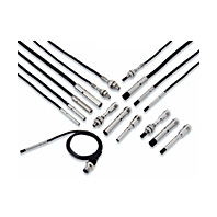 Ultra small size, but surprisingly easy installation!
DC 3-Wire
PREMIUM Model
DC 3-wire (Quadruple/Triple distance model)
Shielded
|
Types |
Quadruple distance model |
||||
|
Size |
M8 |
M12 |
M18 |
M30 |
|
|
Model |
E2E-X4[]8 |
E2E-X9[]12 |
E2E-X14[]18 |
E2E-X23[]30 |
|
|
Sensing distance |
4 mm±10% |
9 mm±10% |
14 mm±10% |
23 mm±10% |
|
|
Setting distance |
0 to 3 mm |
0 to 6.8 mm |
0 to 10.6 mm |
0 to 17.6 mm |
|
|
Differential travel |
15% max. of sensing distance |
||||
|
Detectable object |
Ferrous metals (For non-ferrous metals, refer to the Engineering Data on Catalog.) |
||||
|
Standard sensing object |
Iron, |
Iron, |
Iron, |
Iron, |
|
|
Response frequency *1 |
700 Hz |
700 Hz |
350 Hz |
200 Hz |
|
|
Power supply voltage |
10 to 30 VDC (including 10% ripple (p-p)), Class 2 |
||||
|
Current consumption |
1-output models: 16 mA max. |
||||
|
Output configuration |
B[] Models: PNP open collector, C[] Models: NPN open collector |
||||
|
Operation mode |
1-output models (B1, C1): NO (Normally open), |
||||
|
Control |
Load current |
1-output models: |
|||
|
Residual voltage |
1-output models: |
||||
|
Indicator *2 |
In the Standard I/O mode (SIO mode): Operation indicator (orange, lit) and |
||||
|
Protection circuits |
Power supply reverse polarity protection, Surge suppressor, Output short-circuit |
||||
|
Ambient temperature range |
Operating: -25 to 60°C |
Operating/Storage: -25 to 70°C (with no icing or |
|||
|
Ambient humidity range |
Operating/Storage: 35% to 95% (with no condensation) |
||||
|
Temperature influence |
-15% to 25% max. of |
±15% max. of sensing distance at 23°C in the temperature |
|||
|
Voltage influence |
±1% max. of sensing distance at rated voltage in the rated voltage ±15% range |
||||
|
Insulation resistance |
50 MΩ min. (at 500 VDC) between current-carrying parts and case |
||||
|
Dielectric strength |
1,000 VAC, 50/60 Hz for 1 minute between current-carrying parts and case |
||||
|
Vibration resistance |
10 to 55 Hz, 1.5-mm double amplitude for 2 hours each in X, Y, and Z directions |
||||
|
Shock resistance |
500 m/s2 10 times |
1,000 m/s2 10 times each in X, Y, and Z directions |
|||
|
Degree of protection |
Pre-wired Models, Pre-wired Connector Models: IEC 60529: IP67, ISO 20653 (old |
||||
|
Connection method |
Pre-wired Models (Standard cable length: 2 m), Pre-wired Connector Models (Standard |
||||
|
Weight*4 |
Pre-wired |
Approx. 85 g |
Approx. 95 g |
Approx. 180 g |
Approx. 260 g |
|
M12 Pre-wired |
Approx. 55 g |
Approx. 70 g |
Approx. 115 g |
Approx. 200 g |
|
|
Connector |
Approx. 40 g |
Approx. 55 g |
Approx. 95 g |
Approx. 180 g |
|
|
Materials |
Case |
Nickel-plated brass |
|||
|
Sensing surface |
Polybutylene terephthalat (PBT) |
||||
|
Clamping nuts |
Nickel-plated brass |
||||
|
Toothed washers |
Zinc-plated iron |
||||
|
Cable |
Vinyl chloride (PVC) |
||||
|
Main IO-Link functions*2 |
Operation mode switching between NO and NC, self diagnosis enabling, excessive |
||||
|
IO-Link |
IO-Link |
Ver 1.1 |
|||
|
Baud rate |
COM2 (38.4 kbps), COM3 (230.4 kbps) |
||||
|
Data length |
PD size: 2 bytes, OD size: 1 byte (M-sequence type: TYPE_2_2) |
||||
|
Minimum cycle |
COM2: 2.3 ms, COM3: 0.4 ms |
||||
|
Accessories |
Instruction manual, Clamping nuts, Toothed washer |
||||
|
Types |
Triple distance model |
||||
|
Size |
M8 |
M12 |
M18 |
M30 |
|
|
Model |
E2E-X3[]8 |
E2E-X6[]12 |
E2E-X12[]18 |
E2E-X22[]30 |
|
|
Sensing distance |
3 mm±10% |
6 mm±10% |
12 mm±10% |
22 mm±10% |
|
|
Setting distance |
0 to 2.4 mm |
0 to 4.8 mm |
0 to 9.6 mm |
0 to 16.8 mm |
|
|
Differential travel |
15% max. of sensing distance |
||||
|
Detectable object |
Ferrous metals (For non-ferrous metals, refer to the Engineering Data on Catalog.) |
||||
|
Standard sensing object |
Iron, |
Iron, |
Iron, |
Iron, |
|
|
Response frequency *1 |
1,000 Hz |
800 Hz |
500 Hz |
200 Hz |
|
|
Power supply voltage |
10 to 30 VDC (including 10% ripple (p-p)), Class 2 |
||||
|
Current consumption |
1-output models: |
1-output models: 16 mA max., |
|||
|
Output configuration |
B[] Models: PNP open collector, C[] Models: NPN open collector |
||||
|
Operation mode |
1-output models (B1, |
1-output models (B1, C1): NO (Normally open), |
|||
|
Control |
Load current |
1-output models: |
1-output models: |
||
|
Residual voltage |
1-output models: 2 V |
1-output models: |
|||
|
Indicator *2 |
In the Standard I/O mode (SIO mode): Operation indicator (orange, lit) and |
||||
|
Protection circuits |
Power supply reverse polarity protection, Surge suppressor, Output short-circuit |
||||
|
Ambient temperature range |
Operating/Storage: -25 to 70°C (with no icing or condensation) |
||||
|
Ambient humidity range |
Operating/Storage: 35% to 95% (with no condensation) |
||||
|
Temperature influence |
±10% max. of sensing distance at 23°C in the temperature range of -25 to 70°C |
||||
|
Voltage influence |
±1% max. of sensing distance at rated voltage in the rated voltage ±15% range |
||||
|
Insulation resistance |
50 MΩ min. (at 500 VDC) between current-carrying parts and case |
||||
|
Dielectric strength |
1,000 VAC, 50/60 Hz for 1 minute between current-carrying parts and case |
||||
|
Vibration resistance |
10 to 55 Hz, 1.5-mm double amplitude for 2 hours each in X, Y, and Z directions |
||||
|
Shock resistance |
500 m/s2 10 times |
1,000 m/s2 10 times each in X, Y, and Z directions |
|||
|
Degree of protection |
Pre-wired Models, Pre-wired Connector Models: IEC 60529: IP67, ISO 20653 (old |
||||
|
Connection method |
Pre-wired Models (Standard cable length: 2 m), Pre-wired Connector Models (Standard |
||||
|
Weight*4 |
Pre-wired |
Approx. 85 g |
Approx. 95 g |
Approx. 180 g |
Approx. 260 g |
|
M12 Pre-wired |
Approx. 55 g |
Approx. 70 g |
Approx. 115 g |
Approx. 200 g |
|
|
Connector |
Approx. 40 g |
Approx. 55 g |
Approx. 95 g |
Approx. 180 g |
|
|
Materials |
Case |
Nickel-plated brass |
|||
|
Sensing surface |
Polybutylene terephthalat (PBT) |
||||
|
Clamping nuts |
Nickel-plated brass |
||||
|
Toothed washers |
Zinc-plated iron |
||||
|
Cable |
Vinyl chloride (PVC) |
||||
|
Main IO-Link functions*2 |
Operation mode switching between NO and NC, self diagnosis enabling, excessive |
||||
|
IO-Link |
IO-Link |
Ver 1.1 |
|||
|
Baud rate |
COM2 (38.4 kbps), COM3 (230.4 kbps) |
||||
|
Data length |
PD size: 2 bytes, OD size: 1 byte (M-sequence type: TYPE_2_2) |
||||
|
Minimum cycle |
COM2: 2.3 ms, COM3: 0.4 ms |
||||
|
Accessories |
Instruction manual, Clamping nuts, Toothed washer |
||||
1. The response frequency is an average value. Measurement conditions are as follows: standard sensing object, a distance of twice the standard sensing object, and a set distance of half the sensing distance.
2. IO-Link is not supported for NC-type PNP outputs or all types of NPN outputs.
3. The Oil-resistant Component Evaluation Standards are OMRON's own durability evaluation standards. 2-year oil resistance indicates the median value of the product design and the oil-resistance performance criterion result (=Typical value). The Pre-wired Connector Model verifies 2 years of oil resistance when mating with Round Oil-resistant Connectors XS5 NEXT series correctly. The degree of protection is not satisfied with the part where cable wires are uncovered for the Pre-wired Models.
4. Weight of the standard body-sized model.
DC 3-wire (Quadruple/Triple distance model)
Unshielded
|
Types |
Quadruple distance model |
||||
|
Size |
M8 |
M12 |
M18 |
M30 |
|
|
Model |
E2E-X8M[]8 |
E2E-X16M[]12 |
E2E-X30M[]18 |
E2E-X50M[]30 |
|
|
Sensing distance |
8 mm±10% |
16 mm±10% |
30 mm±10% |
50 mm±10% |
|
|
Setting distance |
0 to 6 mm |
0 to 12.2 mm |
0 to 23 mm |
0 to 38.2 mm |
|
|
Differential travel |
15% max. of sensing distance |
||||
|
Detectable object |
Ferrous metals (For non-ferrous metals, refer to the Engineering Data on Catalog.) |
||||
|
Standard sensing object |
Iron, |
Iron, |
Iron, |
Iron, |
|
|
Response frequency *1 |
500 Hz |
400 Hz |
200 Hz |
100 Hz |
|
|
Power supply voltage |
10 to 30 VDC (including 10% ripple (p-p)), Class 2 |
||||
|
Current consumption |
1-output models: 16 mA max. |
||||
|
Output configuration |
B[] Models: PNP open collector |
||||
|
Operation mode |
1-output models (B1, C1): NO (Normally open), |
||||
|
Control |
Load current |
1-output models: |
|||
|
Residual voltage |
1-output models: |
||||
|
Indicator *2 |
In the Standard I/O mode (SIO mode): Operation indicator (orange, lit) and |
||||
|
Protection circuits |
Power supply reverse polarity protection, Surge suppressor, Output short-circuit |
||||
|
Ambient temperature range |
Operating/Storage: -25 to 70°C (with no icing or condensation) |
||||
|
Ambient humidity range |
Operating/Storage: 35% to 95% (with no condensation) |
||||
|
Temperature influence |
±15% max. of sensing distance at 23°C in the temperature range of -25 to 70°C |
||||
|
Voltage influence |
±1% max. of sensing distance at rated voltage in the rated voltage ±15% range |
||||
|
Insulation resistance |
50 MΩ min. (at 500 VDC) between current-carrying parts and case |
||||
|
Dielectric strength |
1,000 VAC, 50/60 Hz for 1 minute between current-carrying parts and case |
||||
|
Vibration resistance |
10 to 55 Hz, 1.5-mm double amplitude for 2 hours each in X, Y, and Z directions |
||||
|
Shock resistance |
500 m/s2 10 times |
1,000 m/s2 10 times each in X, Y, and Z directions |
|||
|
Degree of protection |
Pre-wired Models, Pre-wired Connector Models: IEC 60529:IP67, ISO 20653 (old |
||||
|
Connection method |
Pre-wired Models (Standard cable length: 2 m), Pre-wired Connector Models |
||||
|
Weight*4 |
Pre-wired |
Approx. 85 g |
Approx. 95 g |
Approx. 190 g |
Approx. 310 g |
|
M12 Pre-wired |
Approx. 55 g |
Approx. 70 g |
Approx. 125 g |
Approx. 250 g |
|
|
Connector |
Approx. 40 g |
Approx. 55 g |
Approx. 105 g |
Approx. 230 g |
|
|
Materials |
Case |
Stainless (SUS303) |
Nickel-plated brass |
||
|
Sensing surface |
Polybutylene terephthalat (PBT) |
||||
|
Clamping nuts |
Nickel-plated brass |
||||
|
Toothed washers |
Zinc-plated iron |
||||
|
Cable |
Vinyl chloride (PVC) |
||||
|
Main IO-Link functions*2 |
Operation mode switching between NO and NC, self diagnosis enabling, excessive |
||||
|
IO-Link |
IO-Link |
Ver1.1 |
|||
|
Baud rate |
COM2 (38.4 kbps), COM3 (230.4 kbps) |
||||
|
Data length |
PD size: 2 bytes, OD size: 1 byte (M-sequence type: TYPE_2_2) |
||||
|
Minimum cycle |
COM2: 2.3 ms, COM3: 0.4 ms |
||||
|
Accessories |
Instruction manual, Clamping nuts, Toothed washer |
||||
|
Types |
Triple distance model |
||||
|
Size |
M8 |
M12 |
M18 |
M30 |
|
|
Model |
E2E-X6M[]8 |
E2E-X10M[]12 |
E2E-X20M[]18 |
E2E-X40M[]30 |
|
|
Sensing distance |
6 mm±10% |
10 mm±10% |
20 mm±10% |
40 mm±10% |
|
|
Setting distance |
0 to 4.8 mm |
0 to 8 mm |
0 to 16 mm |
0 to 32 mm |
|
|
Differential travel |
15% max. of sensing distance |
||||
|
Detectable object |
Ferrous metals (For non-ferrous metals, refer to the Engineering Data on Catalog.) |
||||
|
Standard sensing object |
Iron, |
Iron, |
Iron, |
Iron, |
|
|
Response frequency *1 |
800 Hz |
400 Hz |
200 Hz |
100 Hz |
|
|
Power supply voltage |
10 to 30 VDC (including 10% ripple (p-p)), Class 2 |
||||
|
Current consumption |
1-output models: |
1-output models: 16 mA max., |
|||
|
Output configuration |
B[] Models: PNP open collector |
||||
|
Operation mode |
1-output models (B1, |
1-output models (B1, C1): NO (Normally open), |
|||
|
Control |
Load current |
1-output models: |
1-output models: 10 to 30 VDC, Class 2, 100 mA max., |
||
|
Residual voltage |
1-output models: 2 V |
1-output models: |
|||
|
Indicator *2 |
In the Standard I/O mode (SIO mode): Operation indicator (orange, lit) and |
||||
|
Protection circuits |
Power supply reverse polarity protection, Surge suppressor, Output short-circuit |
||||
|
Ambient temperature range |
Operating/Storage: -25 to 70°C (with no icing or condensation) |
||||
|
Ambient humidity range |
Operating/Storage: 35% to 95% (with no condensation) |
||||
|
Temperature influence |
±10% max. of sensing distance at 23°C in the temperature range of -25 to 70°C |
||||
|
Voltage influence |
±1% max. of sensing distance at rated voltage in the rated voltage ±15% range |
||||
|
Insulation resistance |
50 MΩ min. (at 500 VDC) between current-carrying parts and case |
||||
|
Dielectric strength |
1,000 VAC, 50/60 Hz for 1 minute between current-carrying parts and case |
||||
|
Vibration resistance |
10 to 55 Hz, 1.5-mm double amplitude for 2 hours each in X, Y, and Z directions |
||||
|
Shock resistance |
500 m/s2 10 times |
1,000 m/s2 10 times each in X, Y, and Z directions |
|||
|
Degree of protection |
Pre-wired Models, Pre-wired Connector Models: IEC 60529:IP67, ISO 20653 (old |
||||
|
Connection method |
Pre-wired Models (Standard cable length: 2 m), Pre-wired Connector Models |
||||
|
Weight*4 |
Pre-wired |
Approx. 85 g |
Approx. 95 g |
Approx. 190 g |
Approx. 280 g |
|
M12 Pre-wired |
Approx. 55 g |
Approx. 70 g |
Approx. 125 g |
Approx. 220 g |
|
|
Connector |
Approx. 40 g |
Approx. 55 g |
Approx. 105 g |
Approx. 200 g |
|
|
Materials |
Case |
Stainless (SUS303) |
Nickel-plated brass |
||
|
Sensing surface |
Polybutylene terephthalat (PBT) |
||||
|
Clamping nuts |
Nickel-plated brass |
||||
|
Toothed washers |
Zinc-plated iron |
||||
|
Cable |
Vinyl chloride (PVC) |
||||
|
Main IO-Link functions*2 |
Operation mode switching between NO and NC, self diagnosis enabling, excessive |
||||
|
IO-Link |
IO-Link |
Ver1.1 |
|||
|
Baud rate |
COM2 (38.4 kbps), COM3 (230.4 kbps) |
||||
|
Data length |
PD size: 2 bytes, OD size: 1 byte (M-sequence type: TYPE_2_2) |
||||
|
Minimum cycle |
COM2: 2.3 ms, COM3: 0.4 ms |
||||
|
Accessories |
Instruction manual, Clamping nuts, Toothed washer |
||||
1. The response frequency is an average value. Measurement conditions are as follows: standard sensing object, a distance of twice the standard sensing object, and a set distance of half the sensing distance.
2. IO-Link is not supported for NC-type PNP outputs or all types of NPN outputs.
3. The Oil-resistant Component Evaluation Standards are OMRON's own durability evaluation standards. 2-year oil resistance indicates the median value of the product design and the oil-resistance performance criterion result (=Typical value). Actual performance can be expected to decline after two years on average from shipment. The Pre-wired Connector Model verifies 2 years of oil resistance when mating with Round Oil-resistant Connectors XS5 NEXT series correctly. The degree of protection is not satisfied with the part where cable wires are uncovered for the Pre-wired Models.
4. Weight of the standard body-sized model.
BASIC Model
DC 3-wire (Double/Single distance model)
Shielded
|
Types |
Double distance model |
||||
|
Size |
M8 |
M12 |
M18 |
M30 |
|
|
Model |
E2E-X2[]8 |
E2E-X4[]12 |
E2E-X8[]18 |
E2E-X15[]30 |
|
|
Sensing distance |
2 mm±10% |
4 mm±10% |
8 mm±10% |
15 mm±10% |
|
|
Setting distance |
0 to 1.6 mm |
0 to 3.2 mm |
0 to 6.4 mm |
0 to 12 mm |
|
|
Differential travel |
15% max. of sensing distance |
||||
|
Detectable object |
Ferrous metals (For non-ferrous metals, refer to the Engineering Data on Catalog.) |
||||
|
Standard sensing object |
Iron, |
Iron, |
Iron, |
Iron, |
|
|
Response frequency *1 |
1,500 Hz |
1,000 Hz |
500 Hz |
250 Hz |
|
|
Power supply voltage |
10 to 30 VDC (including 10% ripple (p-p)), Class 2 |
||||
|
Current consumption |
1-output models: 16 mA max. |
||||
|
Output configuration |
B[] Models: PNP open collector |
||||
|
Operation mode |
1-output models (B1, C1): NO (Normally open), |
||||
|
Control |
Load current |
1-output models: |
1-output models: |
||
|
Residual voltage |
1-output models: |
1-output models: |
|||
|
Indicator *2 |
In the Standard I/O mode (SIO mode): Operation indicator (orange, lit) and |
||||
|
Protection circuits |
Power supply reverse polarity protection, Surge suppressor, Output short-circuit |
||||
|
Ambient temperature range |
Operating/Storage: -40 to 85°C (with no icing or condensation) |
||||
|
Ambient humidity range |
Operating/Storage: 35% to 95% (with no condensation) |
||||
|
Temperature influence |
±15% max. of sensing distance at 23°C in the temperature range of -40 to 85°C |
||||
|
Voltage influence |
±1% max. of sensing distance at rated voltage in the rated voltage ±15% range |
||||
|
Insulation resistance |
50 MΩ min. (at 500 VDC) between current-carrying parts and case |
||||
|
Dielectric strength |
1,000 VAC, 50/60 Hz for 1 minute between current-carrying parts and case |
||||
|
Vibration resistance |
10 to 55 Hz, 1.5-mm double amplitude for 2 hours each in X, Y, and Z directions |
||||
|
Shock resistance |
500 m/s2 10 times |
1,000 m/s2 10 times each in X, Y, and Z directions |
|||
|
Degree of protection |
Pre-wired Models, Pre-wired Connector Models: IEC 60529:IP67, ISO 20653 (old |
||||
|
Connection method |
Pre-wired Models (Standard cable length: 2 m), Pre-wired Connector Models |
||||
|
Weight *5 |
Pre-wired |
Approx. 85 g |
Approx. 95 g |
Approx. 170 g |
Approx. 240 g |
|
M12 Pre-wired |
Approx. 55 g |
Approx. 70 g |
Approx. 105 g |
Approx. 170 g |
|
|
Connector |
Approx. 40 g |
Approx. 55 g |
Approx. 85 g |
Approx. 160 g |
|
|
Materials |
Case |
Stainless (SUS303) |
Nickel-plated brass |
||
|
Sensing surface |
Polybutylene terephthalat (PBT) |
||||
|
Clamping nuts |
Nickel-plated brass |
||||
|
Toothed washers |
Zinc-plated iron |
||||
|
Cable |
Vinyl chloride (PVC) |
||||
|
Main IO-Link functions *2 |
Operation mode switching between NO and NC, self diagnosis enabling, excessive |
||||
|
IO-Link |
IO-Link |
Ver1.1 |
|||
|
Baud rate |
COM2 (38.4 kbps), COM3 (230.4 kbps) |
||||
|
Data length |
PD size: 2 bytes, OD size: 1 byte (M-sequence type: TYPE_2_2) |
||||
|
Minimum cycle |
COM2: 2.3 ms, COM3: 0.4 ms |
||||
|
Accessories |
Instruction manual, Clamping nuts, Toothed washer |
||||
|
Types |
Single distance model |
||||
|
Size |
M8 |
M12 |
M18 |
M30 |
|
|
Model |
E2E-X1R5[]8 |
E2E-X2[]12 |
E2E-X5[]18 |
E2E-X10[]30 |
|
|
Sensing distance |
1.5 mm±10% |
2 mm±10% |
5 mm±10% |
10 mm±10% |
|
|
Setting distance |
0 to 1.2 mm |
0 to 1.6 mm |
0 to 4 mm |
0 to 8 mm |
|
|
Differential travel |
10% max. of sensing distance |
||||
|
Detectable object |
Ferrous metals (For non-ferrous metals, refer to the Engineering Data on Catalog.) |
||||
|
Standard sensing object |
Iron, |
Iron, |
Iron, |
Iron, |
|
|
Response frequency *1 |
2,000 Hz |
1,500 Hz |
600 Hz |
400 Hz |
|
|
Power supply voltage |
10 to 30 VDC (including 10% ripple (p-p)), Class 2 |
||||
|
Current consumption |
1-output models: 16 mA max. |
||||
|
Output configuration |
B[] Models: PNP open collector |
||||
|
Operation mode |
1-output models (B1, C1): NO (Normally open), |
||||
|
Control |
Load current |
1-output models: |
1-output models: |
||
|
Residual voltage |
1-output models: |
1-output models: |
|||
|
Indicator *2 |
In the Standard I/O mode (SIO mode): Operation indicator (orange, lit) and |
||||
|
Protection circuits |
Power supply reverse polarity protection, Surge suppressor, Output short-circuit |
||||
|
Ambient temperature range |
Operating/Storage: -40 to 85°C (with no icing or condensation) |
||||
|
Ambient humidity range |
Operating/Storage: 35% to 95% (with no condensation) |
||||
|
Temperature influence |
±15% max. of sensing distance at 23°C in the temperature range of -40 to 85°C |
||||
|
Voltage influence |
±1% max. of sensing distance at rated voltage in the rated voltage ±15% range |
||||
|
Insulation resistance |
50 MΩ min. (at 500 VDC) between current-carrying parts and case |
||||
|
Dielectric strength |
1,000 VAC, 50/60 Hz for 1 minute between current-carrying parts and case |
||||
|
Vibration resistance |
10 to 55 Hz, 1.5-mm double amplitude for 2 hours each in X, Y, and Z directions |
||||
|
Shock resistance |
500 m/s2 10 times |
1,000 m/s2 10 times each in X, Y, and Z directions |
|||
|
Degree of protection |
Pre-wired Models, Pre-wired Connector Models: IEC 60529:IP67, ISO 20653 (old |
||||
|
Connection method |
Pre-wired Models (Standard cable length: 2 m), Pre-wired Connector Models |
||||
|
Weight *5 |
Pre-wired |
Approx. 85 g |
Approx. 95 g |
Approx. 170 g |
Approx. 240 g |
|
M12 Pre-wired |
Approx. 55 g |
Approx. 70 g |
Approx. 105 g |
Approx. 170 g |
|
|
Connector |
Approx. 40 g |
Approx. 55 g |
Approx. 85 g |
Approx. 160 g |
|
|
Materials |
Case |
Stainless (SUS303) |
Nickel-plated brass |
||
|
Sensing surface |
Polybutylene terephthalat (PBT) |
||||
|
Clamping nuts |
Nickel-plated brass |
||||
|
Toothed washers |
Zinc-plated iron |
||||
|
Cable |
Vinyl chloride (PVC) |
||||
|
Main IO-Link functions *2 |
Operation mode switching between NO and NC, self diagnosis enabling, excessive |
||||
|
IO-Link |
IO-Link |
Ver1.1 |
|||
|
Baud rate |
COM2 (38.4 kbps), COM3 (230.4 kbps) |
||||
|
Data length |
PD size: 2 bytes, OD size: 1 byte (M-sequence type: TYPE_2_2) |
||||
|
Minimum cycle |
COM2: 2.3 ms, COM3: 0.4 ms |
||||
|
Accessories |
Instruction manual, Clamping nuts, Toothed washer |
||||
1. The response frequency is an average value. Measurement conditions are as follows: standard sensing object, a distance of twice the standard sensing object, and a set distance of half the sensing distance.
2. IO-Link is not supported for NC-type PNP outputs or all types of NPN outputs.
3. Dual-output specification for the M8-size models is only applicable to long-size M12 Connector models.
4. The Oil-resistant Component Evaluation Standards are OMRON's own durability evaluation standards. 2-year oil resistance indicates the median value of the product design and the oil resistance performance criterion result (=Typical value). Actual performance can be expected to decline after two years on average from shipment. The Pre-wired Connector Model verifies 2 years of oil resistance when mating with Round Oil-resistant Connectors XS5 NEXT series
correctly. The degree of protection is not satisfied with the part where cable wires are uncovered for the Pre-wired Models.
5. Weight of the standard body-sized model.
DC 3-wire (Double/Single distance model)
Unshielded
|
Types |
Double distance model |
||||
|
Size |
M8 |
M12 |
M18 |
M30 |
|
|
Model |
E2E-X4M[]8 |
E2E-X8M[]12 |
E2E-X16M[]18 |
E2E-X30M[]30 |
|
|
Sensing distance |
4 mm±10% |
8 mm±10% |
16 mm±10% |
30 mm±10% |
|
|
Setting distance |
0 to 3.2 mm |
0 to 6.4 mm |
0 to 12.8 mm |
0 to 24 mm |
|
|
Differential travel |
15% max. of sensing distance |
||||
|
Detectable object |
Ferrous metals (For non-ferrous metals, refer to the Engineering Data on Catalog.) |
||||
|
Standard sensing object |
Iron, |
Iron, |
Iron, |
Iron, |
|
|
Response frequency *1 |
1,000 Hz |
800 Hz |
400 Hz |
100 Hz |
|
|
Power supply voltage |
10 to 30 VDC (including 10% ripple (p-p)), Class 2 |
||||
|
Current consumption |
1-output models: 16 mA max. |
||||
|
Output configuration |
B[] Models: PNP open collector |
||||
|
Operation mode |
1-output models (B1, C1): NO (Normally open), |
||||
|
Control |
Load current |
1-output models: |
1-output models: |
||
|
Residual voltage |
1-output models: |
1-output models: |
|||
|
Indicator *2 |
In the Standard I/O mode (SIO mode): Operation indicator (orange, lit) and |
||||
|
Protection circuits |
Power supply reverse polarity protection, Surge suppressor, Output short-circuit |
||||
|
Ambient temperature range |
Operating/Storage: -40 to 85°C (with no icing or condensation) |
||||
|
Ambient humidity range |
Operating/Storage: 35% to 95% (with no condensation) |
||||
|
Temperature influence |
±15% max. of sensing distance at 23°C in the temperature range of -40 to 85°C |
||||
|
Voltage influence |
±1% max. of sensing distance at rated voltage in the rated voltage ±15% range |
||||
|
Insulation resistance |
50 MΩ min. (at 500 VDC) between current-carrying parts and case |
||||
|
Dielectric strength |
1,000 VAC, 50/60 Hz for 1 minute between current-carrying parts and case |
||||
|
Vibration resistance |
10 to 55 Hz, 1.5-mm double amplitude for 2 hours each in X, Y, and Z directions |
||||
|
Shock resistance |
500 m/s2 10 times |
1,000 m/s2 10 times each in X, Y, and Z directions |
|||
|
Degree of protection |
Pre-wired Models, Pre-wired Connector Models: IEC 60529:IP67, ISO 20653 (old |
||||
|
Connection method |
Pre-wired Models (Standard cable length: 2 m), Pre-wired Connector Models |
||||
|
Weight *5 |
Pre-wired |
Approx. 85 g |
Approx. 95 g |
Approx. 170 g |
Approx. 280 g |
|
M12 Pre-wired |
Approx. 55 g |
Approx. 70 g |
Approx. 105 g |
Approx. 220 g |
|
|
Connector |
Approx. 40 g |
Approx. 55 g |
Approx. 85 g |
Approx. 200 g |
|
|
Materials |
Case |
Stainless (SUS303) |
Nickel-plated brass |
||
|
Sensing surface |
Polybutylene terephthalat (PBT) |
||||
|
Clamping nuts |
Nickel-plated brass |
||||
|
Toothed washers |
Zinc-plated iron |
||||
|
Cable |
Vinyl chloride (PVC) |
||||
|
Main IO-Link functions *2 |
Operation mode switching between NO and NC, self diagnosis enabling, excessive |
||||
|
IO-Link |
IO-Link |
Ver 1.1 |
|||
|
Baud rate |
COM2 (38.4 kbps), COM3 (230.4 kbps) |
||||
|
Data length |
PD size: 2 bytes, OD size: 1 byte (M-sequence type: TYPE_2_2) |
||||
|
Minimum cycle |
COM2: 2.3 ms, COM3: 0.4 ms |
||||
|
Accessories |
Instruction manual, Clamping nuts, Toothed washer |
||||
|
Types |
Single distance model |
||||
|
Size |
M8 |
M12 |
M18 |
M30 |
|
|
Model |
E2E-X2M[]8 |
E2E-X5M[]12 |
E2E-X10M[]18 |
E2E-X18M[]30 |
|
|
Sensing distance |
2 mm±10% |
5 mm±10% |
10 mm±10% |
18 mm±10% |
|
|
Setting distance |
0 to 1.6 mm |
0 to 4 mm |
0 to 8 mm |
0 to 14.4 mm |
|
|
Differential travel |
10% max. of sensing distance |
||||
|
Detectable object |
Ferrous metals (For non-ferrous metals, refer to the Engineering Data on Catalog.) |
||||
|
Standard sensing object |
Iron, |
Iron, |
Iron, |
Iron, |
|
|
Response frequency *1 |
1,000 Hz |
800 Hz |
400 Hz |
100 Hz |
|
|
Power supply voltage |
10 to 30 VDC (including 10% ripple (p-p)), Class 2 |
||||
|
Current consumption |
1-output models: 16 mA max. |
||||
|
Output configuration |
B[] Models: PNP open collector |
||||
|
Operation mode |
1-output models (B1, C1): NO (Normally open), |
||||
|
Control |
Load current |
1-output models: |
1-output models: |
||
|
Residual voltage |
1-output models: |
1-output models: |
|||
|
Indicator *2 |
In the Standard I/O mode (SIO mode): Operation indicator (orange, lit) and |
||||
|
Protection circuits |
Power supply reverse polarity protection, Surge suppressor, Output short-circuit |
||||
|
Ambient temperature range |
Operating/Storage: -40 to 85°C (with no icing or condensation) |
||||
|
Ambient humidity range |
Operating/Storage: 35% to 95% (with no condensation) |
||||
|
Temperature influence |
±15% max. of sensing distance at 23°C in the temperature range of -40 to 85°C |
||||
|
Voltage influence |
±1% max. of sensing distance at rated voltage in the rated voltage ±15% range |
||||
|
Insulation resistance |
50 MΩ min. (at 500 VDC) between current-carrying parts and case |
||||
|
Dielectric strength |
1,000 VAC, 50/60 Hz for 1 minute between current-carrying parts and case |
||||
|
Vibration resistance |
10 to 55 Hz, 1.5-mm double amplitude for 2 hours each in X, Y, and Z directions |
||||
|
Shock resistance |
500 m/s2 10 times |
1,000 m/s2 10 times each in X, Y, and Z directions |
|||
|
Degree of protection |
Pre-wired Models, Pre-wired Connector Models: IEC 60529:IP67, ISO 20653 (old |
||||
|
Connection method |
Pre-wired Models (Standard cable length: 2 m), Pre-wired Connector Models |
||||
|
Weight *5 |
Pre-wired |
Approx. 85 g |
Approx. 95 g |
Approx. 170 g |
Approx. 240 g |
|
M12 Pre-wired |
Approx. 55 g |
Approx. 70 g |
Approx. 105 g |
Approx. 170 g |
|
|
Connector |
Approx. 40 g |
Approx. 55 g |
Approx. 85 g |
Approx. 160 g |
|
|
Materials |
Case |
Stainless (SUS303) |
Nickel-plated brass |
||
|
Sensing surface |
Polybutylene terephthalat (PBT) |
||||
|
Clamping nuts |
Nickel-plated brass |
||||
|
Toothed washers |
Zinc-plated iron |
||||
|
Cable |
Vinyl chloride (PVC) |
||||
|
Main IO-Link functions *2 |
Operation mode switching between NO and NC, self diagnosis enabling, excessive |
||||
|
IO-Link |
IO-Link |
Ver 1.1 |
|||
|
Baud rate |
COM2 (38.4 kbps), COM3 (230.4 kbps) |
||||
|
Data length |
PD size: 2 bytes, OD size: 1 byte (M-sequence type: TYPE_2_2) |
||||
|
Minimum cycle |
COM2: 2.3 ms, COM3: 0.4 ms |
||||
|
Accessories |
Instruction manual, Clamping nuts, Toothed washer |
||||
1. The response frequency is an average value. Measurement conditions are as follows: standard sensing object, a distance of twice the standard sensing object, and a set distance of half the sensing distance.
2. IO-Link is not supported for NC-type PNP outputs or all types of NPN outputs.
3. Dual-output specification for the M8-size models is only applicable to long-size M12 Connector models.
4. The Oil-resistant Component Evaluation Standards are OMRON's own durability evaluation standards. 2-year oil resistance indicates the median value of the product design and the oil-resistance performance criterion result (=Typical value). Actual performance can be expected to decline after two years on average from shipment. The Pre-wired Connector Model verifies 2 years of oil resistance when mating with Round Oil-resistant Connectors XS5 NEXT series
correctly. The degree of protection is not satisfied with the part where cable wires are uncovered for the Pre-wired Models.
5. Weight of the standard body-sized model.
DC 2-wire (Triple distance model)
DC 2-wire (Triple distance model)
|
Size |
M8 |
M12 |
|||
|
Shielded |
Shielded |
Unshielded |
Shielded |
Unshielded |
|
|
Model |
E2E-X3D[] |
E2E-X6MD[] |
E2E-X7D[] |
E2E-X10MD[] |
|
|
Sensing distance |
3 mm ±10% |
6 mm ±10% |
7 mm ±10% |
10 mm ±10% |
|
|
Setting distance *1 |
0 to 2.4 mm |
0 to 4.8 mm |
0 to 5.6 mm |
0 to 8 mm |
|
|
Differential travel |
15% max. of sensing distance |
||||
|
Detectable object |
Ferrous metal (The sensing distance decreases with non-ferrous metal. Refer to |
||||
|
Standard sensing object |
Iron, |
Iron, |
Iron, |
Iron, |
|
|
Response frequency *2 |
350 Hz |
250 Hz |
350 Hz |
200 Hz |
|
|
Power supply voltage |
10 to 30 VDC, (including 10% ripple (p-p)) |
||||
|
Leakage current |
0.8 mA max. |
||||
|
Control |
Load current |
3 to 100 mA |
|||
|
Residual |
Polarity: 3 V max. (Load current: 100 mA, Cable length: 2 m) |
||||
|
Indicator |
D1 Models: Operation indicator (orange), Setting indicator (green) |
||||
|
Operation mode |
D1 Models: NO |
||||
|
Protection circuits |
Surge suppressor, Load short-circuit protection |
||||
|
Ambient temperature |
Operating: -25 to 70°C, Storage: -40 to 85°C (with no icing or condensation) |
||||
|
Ambient humidity range |
Operating and Storage: 35% to 95% (with no condensation) |
||||
|
Temperature influence |
±10% max. of sensing distance at 23°C in the temperature range of -25 to 70°C |
||||
|
Voltage influence |
±1% max. of sensing distance at rated voltage in the rated voltage ±15% range |
||||
|
Insulation resistance |
50 MΩ min. (at 500 VDC) between current-carrying parts and case |
||||
|
Dielectric strength |
1,000 VAC, 50/60 Hz for 1 minute between current-carrying parts and case |
||||
|
Vibration resistance |
10 to 55 Hz, 1.5-mm double amplitude for 2 hours each in X, Y, and Z directions |
||||
|
Shock resistance |
500 m/s2 10 times each in X, Y, and Z |
1,000 m/s2 10 times each in X, Y, and Z |
|||
|
Degree of protection |
Pre-wired Models/Pre-wired Connector Models: IP67 (IEC 60529), IP67G *3 (JIS C 0920 |
||||
|
Connecting method |
Pre-wired Models (Standard cable length: 2 m) and Pre-wired Connector Models (Standard |
||||
|
Weight |
Pre-wired |
Approx. 60 g |
Approx. 70 g |
||
|
Pre-wired |
Approx. 30 g |
Approx. 40 g |
|||
|
Materials |
Case |
Nickel-plated brass |
Stainless steel |
Nickel-plated brass |
|
|
Sensing |
Polybutylene terephthalate (PBT) |
||||
|
Clamping |
Nickel-plated brass |
||||
|
Toothed |
Zinc-plated iron |
||||
|
Cable |
Vinyl chloride (PVC) |
||||
|
Accessories |
Instruction manual, Clamping nuts, Toothed washer |
||||
|
Size |
M18 |
M30 |
|||
|
Shielded |
Shielded |
Unshielded |
Shielded |
Unshielded |
|
|
Model |
E2E-X11D[] |
E2E-X20MD[] |
E2E-X20D[] |
E2E-X40MD[] |
|
|
Sensing distance |
11 mm ±10% |
20 mm ±10% |
20 mm ±10% |
40 mm ±10% |
|
|
Setting distance *1 |
0 to 8.8 mm |
0 to 16 mm |
0 to 16 mm |
0 to 32 mm |
|
|
Differential travel |
15% max. of sensing distance |
||||
|
Detectable object |
Ferrous metal (The sensing distance decreases with non-ferrous metal. Refer to |
||||
|
Standard sensing object |
Iron, |
Iron, |
Iron, |
Iron, |
|
|
Response frequency *2 |
250 Hz |
200 Hz |
200 Hz |
50 Hz |
|
|
Power supply voltage |
10 to 30 VDC, (including 10% ripple (p-p)) |
||||
|
Leakage current |
0.8 mA max. |
||||
|
Control |
Load current |
3 to 100 mA |
|||
|
Residual |
Polarity: 3 V max. (Load current: 100 mA, Cable length: 2 m) |
||||
|
Indicator |
D1 Models: Operation indicator (orange), Setting indicator (green) |
||||
|
Operation mode |
D1 Models: NO |
||||
|
Protection circuits |
Surge suppressor, Load short-circuit protection |
||||
|
Ambient temperature |
Operating: -25 to 70°C, Storage: -40 to 85°C (with no icing or condensation) |
||||
|
Ambient humidity range |
Operating and Storage: 35% to 95% (with no condensation) |
||||
|
Temperature influence |
±20% max. of sensing |
±10% max. of sensing |
±20% max. of sensing distance at 23°C in |
||
|
Voltage influence |
±1% max. of sensing distance at rated voltage in the rated voltage ±15% range |
||||
|
Insulation resistance |
50 MΩ min. (at 500 VDC) between current-carrying parts and case |
||||
|
Dielectric strength |
1,000 VAC, 50/60 Hz for 1 minute between current-carrying parts and case |
||||
|
Vibration resistance |
10 to 55 Hz, 1.5-mm double amplitude for 2 hours each in X, Y, and Z directions |
||||
|
Shock resistance |
1,000 m/s2 10 times each in X, Y, and Z directions |
||||
|
Degree of protection |
Pre-wired Models/Pre-wired Connector Models: IP67 (IEC 60529), IP67G *3 (JIS C 0920 |
||||
|
Connecting method |
Pre-wired Models (Standard cable length: 2 m) and Pre-wired Connector Models (Standard |
||||
|
Weight |
Pre-wired |
Approx. 130 g |
Approx. 150 g |
Approx. 180 g |
Approx. 210 g |
|
Pre-wired |
Approx. 70 g |
Approx. 90 g |
Approx.110 g |
Approx. 140 g |
|
|
Materials |
Case |
Nickel-plated brass |
|||
|
Sensing |
Polybutylene terephthalate (PBT) |
||||
|
Clamping |
Nickel-plated brass |
||||
|
Toothed |
Zinc-plated iron |
||||
|
Cable |
Vinyl chloride (PVC) |
||||
|
Accessories |
Instruction manual, Clamping nuts, Toothed washer |
||||
1. Use the Sensor within the range in which the setting indicator (green LED) is ON (except D2 Models).
2. The response frequency is an average value. Measurement conditions are as follows: standard sensing object, a distance of twice the standard sensing object, and a set distance of half the sensing distance.
3. The IP67G is the degree of protection which is defined according to the JIS (Japanese Industrial Standards). The IP67 indicates the same level of protection as defined by the IEC, and the G indicates that a device has resistance to oil.
4. The Oil-resistant Component Evaluation Standards are OMRON's own durability evaluation standards. 2-year oil resistance indicates the median value of the product design and the oil-resistance performance criterion result (=Typical value). The Pre-wired Connector Model verifies 2 years of oil resistance when mating with Round Oil-resistant Connectors XS5 NEXT series correctly. The degree of protection is not satisfied with the part where cable wires are uncovered for the Pre-wired Models.
DC 2-wire (Standard/ Double/ Single distance model)
DC 2-wire (Standard model)
|
Size |
M8 |
M12 |
|||
|
Shielded |
Shielded |
Unshielded |
Shielded |
Unshielded |
|
|
Item Model |
E2E-X2D[] |
E2E-X4MD[] |
E2E-X3D[] |
E2E-X8MD[] |
|
|
Sensing distance |
2 mm ±10% |
4 mm ±10% |
3 mm ±10% |
8 mm ±10% |
|
|
Setting distance *1 |
0 to 1.6 mm |
0 to 3.2 mm |
0 to 2.4 mm |
0 to 6.4 mm |
|
|
Differential travel |
15% max. of sensing distance |
10% max. of sensing distance |
|||
|
Detectable object |
Ferrous metal (The sensing distance decreases with non-ferrous metal. Refer to |
||||
|
Standard sensing object |
Iron, |
Iron, |
Iron, |
Iron, |
|
|
Response frequency *2 |
1.5 kHz |
1 kHz |
1 kHz |
0.8 kHz |
|
|
Power supply voltage |
12 to 24 VDC (including 10% ripple (p-p)), Class 2 |
||||
|
Leakage current |
0.8 mA max. |
||||
|
Control |
Load current |
3 to 100 mA |
|||
|
Residual |
Polarity: 3 V max. (Load current: 100 mA, Cable length: 2 m) |
||||
|
Indicator |
D1 Models: Operation indicator (orange), Setting indicator (green) |
||||
|
Operation mode |
D1 Models: NO |
||||
|
Protection circuits |
Surge suppressor, Load short-circuit protection |
||||
|
Ambient temperature range |
Operating: -25 to 70°C, Storage: -40 to 85°C (with no icing or condensation) |
||||
|
Ambient humidity range |
Operating and Storage: 35% to 95% (with no condensation) |
||||
|
Temperature influence |
±10% max. of sensing distance at 23°C in the temperature range of -25 to 70°C |
||||
|
Voltage influence |
±1% max. of sensing distance at rated voltage in the rated voltage ±15% range |
||||
|
Insulation resistance |
50 MΩ min. (at 500 VDC) between current-carrying parts and case |
||||
|
Dielectric strength |
1,000 VAC, 50/60 Hz for 1 minute between current-carrying parts and case |
||||
|
Vibration resistance |
10 to 55 Hz, 1.5-mm double amplitude for 2 hours each in X, Y, and Z directions |
||||
|
Shock resistance |
500 m/s2 10 times each in X, Y, and Z |
1,000 m/s2 10 times each in X, Y, and Z |
|||
|
Degree of protection |
Pre-wired Models/Pre-wired Connector Models: |
||||
|
Connecting method |
Pre-wired Models (Standard cable length: 2 m), Pre-wired Connector Models (Standard |
||||
|
Weight *5 |
Pre-wired Models |
Approx. 60 g |
Approx. 70 g |
||
|
Pre-wired |
Approx. 30 g |
Approx. 40 g |
|||
|
Connector Models |
Approx. 40 g (M8/M12 Connector) |
Approx. 55 g |
|||
|
Materials |
Case |
M8 Size: Stainless steel (SUS303), M12/M18/M30 Size: Nickel-plated brass |
|||
|
Sensing surface |
Polybutylene terephthalate (PBT) |
||||
|
Clamping nuts |
Nickel-plated brass |
||||
|
Toothed washer |
Zinc-plated iron |
||||
|
Cable |
Vinyl chloride (PVC) |
||||
|
Accessories |
Instruction manual, Clamping nuts, Toothed washer |
||||
|
Size |
M18 |
M30 |
|||
|
Shielded |
Shielded |
Unshielded |
Shielded |
Unshielded |
|
|
Item Model |
E2E-X7D[] |
E2E-X14MD[] |
E2E-X10D[] |
E2E-X20MD[] |
|
|
Sensing distance |
7 mm ±10% |
14 mm ±10% |
10 mm ±10% |
20 mm ±10% |
|
|
Setting distance *1 |
0 to 5.6 mm |
0 to 11.2 mm |
0 to 8 mm |
0 to 16 mm |
|
|
Differential travel |
15% max. of sensing distance |
10% max. of sensing distance |
|||
|
Detectable object |
Ferrous metal (The sensing distance decreases with non-ferrous metal. Refer to |
||||
|
Standard sensing object |
Iron, |
Iron, |
Iron, |
Iron, |
|
|
Response frequency *2 |
0.5 kHz |
0.4 kHz |
0.4 kHz |
0.1 kHz |
|
|
Power supply voltage |
12 to 24 VDC (including 10% ripple (p-p)), Class 2 |
||||
|
Leakage current |
0.8 mA max. |
||||
|
Control |
Load current |
3 to 100 mA |
|||
|
Residual |
Polarity: 3 V max. (Load current: 100 mA, Cable length: 2 m) |
||||
|
Indicator |
D1 Models: Operation indicator (orange), Setting indicator (green) |
||||
|
Operation mode |
D1 Models: NO |
||||
|
Protection circuits |
Surge suppressor, Load short-circuit protection |
||||
|
Ambient temperature range |
Operating: -25 to 70°C, Storage: -40 to 85°C (with no icing or condensation) |
||||
|
Ambient humidity range |
Operating and Storage: 35% to 95% (with no condensation) |
||||
|
Temperature influence |
±10% max. of sensing distance at 23°C in the temperature range of -25 to 70°C |
||||
|
Voltage influence |
±1% max. of sensing distance at rated voltage in the rated voltage ±15% range |
||||
|
Insulation resistance |
50 MΩ min. (at 500 VDC) between current-carrying parts and case |
||||
|
Dielectric strength |
1,000 VAC, 50/60 Hz for 1 minute between current-carrying parts and case |
||||
|
Vibration resistance |
10 to 55 Hz, 1.5-mm double amplitude for 2 hours each in X, Y, and Z directions |
||||
|
Shock resistance |
1,000 m/s2 10 times each in X, Y, and Z directions |
||||
|
Degree of protection |
Pre-wired Models/Pre-wired Connector Models: |
||||
|
Connecting method |
Pre-wired Models (Standard cable length: 2 m), Pre-wired Connector Models (Standard |
||||
|
Weight *5 |
Pre-wired Models |
Approx. 130 g |
Approx. 150 g |
Approx. 180 g |
Approx. 210 g |
|
Pre-wired |
Approx. 70 g |
Approx. 90 g |
Approx. 110 g |
Approx. 140 g |
|
|
Connector Models |
Approx. 85 g |
Approx. 80 g |
Approx. 160 g |
Approx. 150 g |
|
|
Materials |
Case |
M8 Size: Stainless steel (SUS303), M12/M18/M30 Size: Nickel-plated brass |
|||
|
Sensing surface |
Polybutylene terephthalate (PBT) |
||||
|
Clamping nuts |
Nickel-plated brass |
||||
|
Toothed washer |
Zinc-plated iron |
||||
|
Cable |
Vinyl chloride (PVC) |
||||
|
Accessories |
Instruction manual, Clamping nuts, Toothed washer |
||||
1. Use the Sensor within the range in which the setting indicator (green LED) is ON (except D2 Models).
2. The response frequency is an average value. Measurement conditions are as follows: standard sensing object, a distance of twice the standard.
3. The IP67G is the degree of protection which is defined according to the JIS (Japanese Industrial Standards). The IP67 indicates the same level of protection as defined by the IEC, and the G indicates that a device has resistance to oil.
4. The Oil-resistant Component Evaluation Standards are OMRON's own durability evaluation standards. 2-year oil resistance indicates the median value of the product design and the oil-resistance performance criterion result (=Typical value).
The Pre-wired Connector Model verifies 2 years of oil resistance when mating with Round Oil-resistant Connectors XS5 NEXT series correctly. The degree of protection is not satisfied with the part where cable wires are uncovered for the Pre-wired Models.
5. Weight of the standard body-sized model.
DC 2-wire (Double distance model)
|
Size |
M12 |
M18 |
M30 |
|||
|
Shielded |
Shielded |
Unshielded |
Shielded |
Shielded |
Unshielded |
|
|
Item Model |
E2E-X4D[] |
E2E-X8D[] |
E2E-X16MD[] |
E2E-X15D[] |
E2E-X30MD[] |
|
|
Sensing distance |
4 mm ±10% |
8 mm ±10% |
16 mm ±10% |
15 mm ±10% |
30 mm ±10% |
|
|
Setting distance *1 |
0 to 3.2 mm |
0 to 6.4 mm |
0 to 12.8 mm |
0 to 12 mm |
0 to 24 mm |
|
|
Differential travel |
15% max. of sensing distance |
|||||
|
Detectable object |
Ferrous metal (The sensing distance decreases with non-ferrous metal. Refer to |
|||||
|
Standard sensing object |
Iron, |
Iron, |
Iron, |
Iron, |
Iron, |
|
|
Response frequency *2 |
1 kHz |
0.5 kHz |
0.4 kHz |
0.25 kHz |
0.1 kHz |
|
|
Power supply voltage |
12 to 24 VDC (including 10% ripple (p-p)), Class 2 |
|||||
|
Leakage current |
0.8 mA max. |
|||||
|
Control |
Load current |
3 to 100 mA |
||||
|
Residual |
5 V max. (Load current: 100 mA, Cable length: 2 m) |
|||||
|
Indicator |
D1 Models: Operation indicator (orange), Setting indicator (green) |
|||||
|
Operation mode |
D1 Models: NO |
|||||
|
Protection circuits |
Surge suppressor, Load short-circuit protection |
|||||
|
Ambient temperature |
Operating: -25 to 70°C, Storage: -40 to 85°C (with no icing or condensation) |
|||||
|
Ambient humidity range |
Operating and Storage: 35% to 95% (with no condensation) |
|||||
|
Temperature influence |
±10% max. of sensing distance at 23°C in the temperature range of -25 to 70°C |
|||||
|
Voltage influence |
±1% max. of sensing distance at rated voltage in the rated voltage ±15% range |
|||||
|
Insulation resistance |
50 MΩ min. (at 500 VDC) between current-carrying parts and case |
|||||
|
Dielectric strength |
1,000 VAC, 50/60 Hz for 1 minute between current-carrying parts and case |
|||||
|
Vibration resistance |
10 to 55 Hz, 1.5-mm double amplitude for 2 hours each in X, Y, and Z directions |
|||||
|
Shock resistance |
500 m/s2 10 times |
1,000 m/s2 10 times each in X, Y, and Z directions |
||||
|
Degree of protection |
Pre-wired Models/Pre-wired Connector Models: |
|||||
|
Connecting method |
Pre-wired Models (Standard cable length: 2 m), Pre-wired Connector Models (Standard |
|||||
|
Weight |
Pre-wired |
Approx. 70 g |
Approx. 130 g |
Approx. 150 g |
Approx. 180 g |
Approx. 210 g |
|
Pre-wired |
Approx. 40 g |
Approx. 70 g |
Approx. 90 g |
Approx. 110 g |
Approx. 140 g |
|
|
Materials |
Case |
Nickel-plated brass |
||||
|
Sensing surface |
Polybutylene terephthalate (PBT) |
|||||
|
Clamping nuts |
Nickel-plated brass |
|||||
|
Toothed washer |
Zinc-plated iron |
|||||
|
Cable |
Vinyl chloride (PVC) |
|||||
|
Accessories |
Instruction manual, Clamping nuts, Toothed washer |
|||||
1. Use the Sensor within the range in which the setting indicator (green LED) is ON (except D2 Models).
2. The response frequency is an average value. Measurement conditions are as follows: standard sensing object, a distance of twice the standard.
3. The IP67G is the degree of protection which is defined according to the JIS (Japanese Industrial Standards). The IP67 indicates the same level of protection as defined by the IEC, and the G indicates that a device has resistance to oil.
4. The Oil-resistant Component Evaluation Standards are OMRON's own durability evaluation standards. 2-year oil resistance indicates the median value of the product design and the oil-resistance performance criterion result (=Typical value).
The Pre-wired Connector Model verifies 2 years of oil resistance when mating with Round Oil-resistant Connectors XS5 NEXT series correctly.
The degree of protection is not satisfied with the part where cable wires are uncovered for the Pre-wired Models.
DC 2-wire (Single distance model)
|
Size |
M8 |
M12 |
M18 |
|
|
Shielded |
Shielded |
|||
|
Model |
E2E-X1R5D[] |
E2E-X2R5D[] |
E2E-X5D[] |
|
|
Sensing distance |
1.5 mm ±10% |
2.5 mm ±10% |
5 mm ±10% |
|
|
Setting distance *1 |
0 to 1.2 mm |
0 to 2 mm |
0 to 4 mm |
|
|
Differential travel |
10% max. of sensing distance |
|||
|
Detectable object |
Ferrous metal (The sensing distance decreases with non-ferrous metal. Refer to |
|||
|
Standard sensing object |
Iron, 10 × 10 × 1 mm |
Iron, 12 × 12 × 1 mm |
Iron, 18 × 18 × 1 mm |
|
|
Response frequency *2 |
250 Hz |
250 Hz |
250 Hz |
|
|
Power supply voltage |
10 to 30 VDC, (including 10% ripple (p-p)) |
|||
|
Leakage current |
0.8 mA max. |
|||
|
Control |
Load current |
3 to 100 mA |
||
|
Residual |
Polarity: 3 V max. (Load current: 100 mA, Cable length: 2 m) |
|||
|
Indicator |
D1 Models: Operation indicator (orange), Setting indicator (green) |
|||
|
Operation mode |
D1 Models: NO |
|||
|
Protection circuits |
Surge suppressor, Load short-circuit protection |
|||
|
Ambient temperature |
Operating: -25 to 70°C, Storage: -40 to 85°C (with no icing or condensation) |
|||
|
Ambient humidity range |
Operating and Storage: 35% to 95% (with no condensation) |
|||
|
Temperature influence |
±10% max. of sensing distance at 23°C in the temperature range of -25 to 70°C |
|||
|
Voltage influence |
±1% max. of sensing distance at rated voltage in the rated voltage ±15% range |
|||
|
Insulation resistance |
50 MΩ min. (at 500 VDC) between current-carrying parts and case |
|||
|
Dielectric strength |
1,000 VAC, 50/60 Hz for 1 minute between current-carrying parts and case |
|||
|
Vibration resistance |
10 to 55 Hz, 1.5-mm double amplitude for 2 hours each in X, Y, and Z directions |
|||
|
Shock resistance |
500 m/s2 10 times each in X, |
1,000 m/s2 10 times each in X, Y, and Z directions |
||
|
Degree of protection |
Pre-wired Models/Pre-wired Connector Models: IP67 (IEC 60529), IP67G *3 (JIS C 0920 |
|||
|
Connecting method |
Pre-wired Models (Standard cable length: 2 m) and Pre-wired Connector Models (Standard |
|||
|
Weight |
Pre-wired |
Approx. 60 g |
Approx. 70 g |
Approx. 130 g |
|
Pre-wired |
Approx. 30 g |
Approx. 40 g |
Approx. 70 g |
|
|
Materials |
Case |
Stainless steel (SUS303) |
Nickel-plated brass |
|
|
Sensing |
Polybutylene terephthalate (PBT) |
|||
|
Clamping |
Nickel-plated brass |
|||
|
Toothed |
Zinc-plated iron |
|||
|
Cable |
Vinyl chloride (PVC) |
|||
|
Accessories |
Instruction manual, Clamping nuts, Toothed washer |
|||
1. Use the Sensor within the range in which the setting indicator (green LED) is ON (except D2 Models).
2. The response frequency is an average value. Measurement conditions are as follows: standard sensing object, a distance of twice the standard.
3. The IP67G is the degree of protection which is defined according to the JIS (Japanese Industrial Standards). The IP67 indicates the same level of protection as defined by the IEC, and the G indicates that a device has resistance to oil.
4. The Oil-resistant Component Evaluation Standards are OMRON's own durability evaluation standards. 2-year oil resistance indicates the median value of the product design and the oil-resistance performance criterion result (=Typical value). The Pre-wired Connector Model verifies 2 years of oil resistance when mating with Round Oil-resistant Connectors XS5 NEXT series correctly. The degree of protection is not satisfied with the part where cable wires are uncovered for the Pre-wired Models.