


Oil-resistant Proximity Sensors
E2ER / E2ERZ
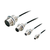 Proximity Sensors That Withstand Cutting Oil to Reduce Failures Caused by Ingress of Cutting Oil
Standard Proximity Sensors
|
Size |
M8 |
M12 |
M18 |
M30 |
|
|
Shielded |
Shielded |
||||
|
Model |
E2ER-X2D[] |
E2ER-X3D[] |
E2ER-X7D[] |
E2ER-X10D[] |
|
|
Sensing distance |
2 mm ±10% |
3 mm ±10% |
7 mm ±10% |
10 mm ±10% |
|
|
Set distance *1 |
0 to 1.6 mm |
0 to 2.4 mm |
0 to 5.6 mm |
0 to 8 mm |
|
|
Differential travel |
15% max. of sensing distance |
10% max. of sensing distance |
|||
|
Detectable object |
Ferrous metal (The sensing distance decreases with non-ferrous metal. Refer to Engineering Data on Catalog.) |
||||
|
Standard sensing object |
Iron, 8 × 8 × 1 mm |
Iron, 12 × 12 × 1 mm |
Iron, 18 × 18 × 1 mm |
Iron, 30 × 30 × 1 mm |
|
|
Response frequency *2 |
1.5 kHz |
1 kHz |
0.5 kHz |
0.4 kHz |
|
|
Power supply voltage |
10 to 30 VDC, (including 10% ripple (p-p)) |
||||
|
Leakage current |
0.8 mA max. |
||||
|
Control |
Load current |
3 to 100 mA |
|||
|
Residual voltage |
3 V max. (Load current: 100 mA, Cable length: 2 m) |
||||
|
Indicators |
D1 Models: Operation indicator (red), Setting indicator (green) |
||||
|
Operation mode |
D1 Models: NO |
||||
|
Protection circuits |
Surge suppressor, Load short-circuit protection |
||||
|
Ambient temperature range |
Operating: -25 to 70°C, Storage: -40 to 85°C (with no icing or condensation) |
||||
|
Ambient humidity range |
Operating and Storage: 35% to 95% (with no condensation) |
||||
|
Temperature influence |
±15% max. of sensing distance |
±10% max. of sensing distance at 23°C in the temperature range of -25 to 70°C |
|||
|
Voltage influence |
±1% max. of sensing distance at rated voltage in the rated voltage ±15% range |
||||
|
Insulation resistance |
50 MΩ min. (at 500 VDC) between current-carrying parts and case |
||||
|
Dielectric strength |
1,000 VAC, 50/60 Hz for 1 minute between current-carrying parts and case |
||||
|
Vibration resistance (destruction) |
10 to 55 Hz, 1.5-mm double amplitude for 2 hours each in X, Y, and Z directions |
||||
|
Shock resistance (destruction) |
500 m/s2 10 times |
1,000 m/s2 10 times each in X, Y, and Z directions |
|||
|
Degree of protection |
IP67 (IEC 60529) and IP67G *3 (JIS C 0920 Annex 1) |
||||
|
Connection method |
Pre-wired Models (Standard cable length: 2 m) and Pre-wired Connector Models (Standard cable length: 300 mm) |
||||
|
Weight |
Pre-wired Models |
Approx. 65 g |
Approx. 75 g |
Approx. 145 g |
Approx. 215 g |
|
Pre-wired Connector Models |
Approx. 30 g |
Approx. 40 g |
Approx. 90 g |
Approx. 155 g |
|
|
Materials |
Case |
Stainless steel (SUS303) |
Nickel-plated brass |
||
|
Sensing surface |
Polybutylene terephthalate (PBT) |
||||
|
Clamping nuts |
Nickel-plated brass |
||||
|
Toothed washer |
Zinc-plated iron |
||||
|
Accessories |
Instruction manual |
||||
1. Use the Sensor within the range in which the setting indicator (green LED) is ON (except D2 Models).
2. The response frequency is an average value.
Measurement conditions are as follows: standard sensing object, a distance of twice the standard sensing object, and a set distance of half the sensing distance.
3. The IP67G is the degree of protection which is defined according to the JIS (Japanese Industrial Standards).
The IP67 indicates the same level of protection as defined by the IEC, and the G indicates that a device has resistance to oil.
4. The Oil-resistant Component Evaluation Standards are OMRON's own durability evaluation standards.
The Pre-wired Connector Model meets the degree of protection when it is correctly connected with an XS5[]R Oil-resistant Connector.
The degree of protection is not satisfied with the part where there is no XS5FR Oil-resistant Connector connected and cable wires are uncovered.
And as for the Pre-wired Models, the degree of protection is not satisfied with the part where cable wires are uncovered.
Chip-immune Proximity Sensors
|
Size |
M12 |
M18 |
M30 |
|
|
Shielded |
Shielded |
|||
|
Model |
E2ERZ-X2D[] |
E2ERZ-X4D[] |
E2ERZ-X8D[] |
|
|
Sensing distance |
2 mm ±10% |
4 mm ±10% |
8 mm ±10% |
|
|
Set distance *1 |
0 to 1.6 mm |
0 to 3.2 mm |
0 to 6.4 mm |
|
|
Differential travel |
20% max. of sensing distance |
|||
|
Detectable object |
Ferrous metal (The sensing distance decreases with non-ferrous metal. Refer to Engineering Data on Catalog.) |
|||
|
Standard sensing object |
Iron, 12 × 12 × 1 mm |
Iron, 30 × 30 × 1 mm |
Iron, 54 × 54 × 1 mm |
|
|
Response frequency *2 |
200 Hz |
100 Hz |
30 Hz |
|
|
Power supply voltage |
10 to 30 VDC, (including 10% ripple (p-p)) |
|||
|
Leakage current |
0.8 mA max. |
|||
|
Control |
Load current |
3 to 100 mA |
||
|
Residual voltage |
3 V max. (Load current: 100 mA, Cable length: 2 m) |
|||
|
Indicators |
D1 Models: Operation indicator (red), Setting indicator (green) |
|||
|
Operation mode |
D1 Models: NO |
|||
|
Protection circuits |
Surge suppressor, Load short-circuit protection |
|||
|
Ambient temperature range |
Operating and Storage: 0 to 50°C (with no icing or condensation) |
|||
|
Ambient humidity range |
Operating and Storage: 35% to 95% (with no condensation) |
|||
|
Temperature influence |
±20% max. of sensing distance at 23°C in the temperature range of 0 to 50°C |
|||
|
Voltage influence |
±2.5% max. of sensing distance at rated voltage in the rated voltage ±10% range |
|||
|
Insulation resistance |
50 MΩ min. (at 500 VDC) between current-carrying parts and case |
|||
|
Dielectric strength |
1,000 VAC, 50/60 Hz for 1 minute between current-carrying parts and case |
|||
|
Vibration resistance (destruction) |
10 to 55 Hz, 1.5-mm double amplitude for 2 hours each in X, Y, and Z directions |
|||
|
Shock resistance (destruction) |
1,000 m/s2 10 times each in X, Y, and Z directions |
|||
|
Degree of protection |
IP67 (IEC 60529) and IP67G *3 (JIS C 0920 Annex 1) |
|||
|
Connection method |
Pre-wired Models (Standard cable length: 2 m) and Pre-wired Connector Models (Standard cable length: 300 mm) |
|||
|
Weight |
Pre-wired Models |
Approx. 75 g |
Approx. 145 g |
Approx. 215 g |
|
Pre-wired Connector Models |
Approx. 40 g |
Approx. 90 g |
Approx. 155 g |
|
|
Materials |
Case |
Nickel-plated brass |
||
|
Sensing surface |
Polybutylene terephthalate (PBT) |
|||
|
Clamping nuts |
Zinc-plated iron |
|||
|
Toothed washer |
Zinc-plated iron |
|||
|
Accessories |
Instruction manual |
|||
1. Use the Sensor within the range in which the setting indicator (green LED) is ON (except D2 Models).
2. The response frequency is an average value.
Measurement conditions are as follows: standard sensing object, a distance of twice the standard sensing object, and a set distance of half the sensing distance.
3. The IP67G is the degree of protection which is defined according to the JIS (Japanese Industrial Standards).
The IP67 indicates the same level of protection as defined by the IEC, and the G indicates that a device has resistance to oil.
4. The Oil-resistant Component Evaluation Standards are OMRON's own durability evaluation standards.
The Pre-wired Connector Model meets the degree of protection when it is correctly connected with an XS5[]R Oil-resistant Connector.
The degree of protection is not satisfied with the part where there is no XS5FR Oil-resistant Connector connected and cable wires are uncovered.
And as for the Pre-wired Models, the degree of protection is not satisfied with the part where cable wires are uncovered.