


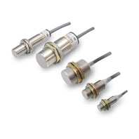
Chip-immune Inductive Proximity Sensor
E2EZ
 Chip-immune Inductive Proximity Sensor
|
Model |
E2EZ-X2D[]-N |
E2EZ-X4D[]-N |
E2EZ-X8D[]-N |
E2EZ-X4C1 |
E2EZ-X8C1 |
|
|
Sensing distance |
2 mm ±10% |
4 mm ±10% |
8 mm ±10% |
4 mm ±10% |
8 mm ±10% |
|
|
Set distance *1 |
0 to 1.6 mm |
0 to 3.2 mm |
0 to 6.4 mm |
0 to 3.2 mm |
0 to 6.4 mm |
|
|
Differential travel |
20% max. of sensing distance |
|||||
|
Detectable object |
Ferrous metal (The sensing distance decreases with non-ferrous metal. Refer to Engineering |
|||||
|
Standard sensing |
Iron, 12 × 12 × 1 mm |
Iron, 30 × 30 × 1 mm |
Iron, 54 × 54 × 1 mm |
Iron, 30 × |
Iron, 54 × |
|
|
Response |
200 Hz |
100 Hz |
30 Hz |
12 Hz |
8 Hz |
|
|
Power supply volt- |
12 to 24 VDC (10 to 30 VDC), ripple (p-p): 10% max. |
12 to 24 VDC (10 to 30 VDC), |
||||
|
Current |
--- |
15 mA max. |
||||
|
Leakage current |
0.8 mA max. |
--- |
||||
|
Control |
Load |
3 to 100 mA max. |
NPN open-collector output/ |
|||
|
Residual |
3 V max. (Load current: 100 mA, Cable length: 2 m) |
2 V max. (Load current: 200 mA, |
||||
|
Indicators |
D1 Models: Operation indicator (red), Setting indicator (green) |
Detection indicator (red) |
||||
|
Operation mode |
D1 Models: NO |
NO |
||||
|
Protection |
Load short-circuit protection, Surge suppressor |
Load short-circuit protection, |
||||
|
Ambient |
Operating/Storage: 0 to 50°C (with no icing or condensation) |
|||||
|
Ambient |
Operating/Storage: 35% to 95% (with no condensation) |
|||||
|
Temperature |
±20% max. of sensing distance at 23°C in the temperature range of 0 to 50°C |
|||||
|
Voltage influence |
±2.5% max. of sensing distance at rated voltage in the rated voltage ±10% range |
|||||
|
Insulation |
50 MΩ min. (at 500 VDC) between current-carrying parts and case |
|||||
|
Dielectric |
1,000 VAC, 50/60 Hz for 1 minute between current-carrying parts and case |
|||||
|
Vibration |
Destruction: 10 to 55 Hz, 1.5-mm double amplitude for 2 hours each in X, Y, and Z directions |
|||||
|
Shock resistance |
Destruction: 1,000 m/s2 10 times each in X, Y, and Z directions |
|||||
|
Degree of |
IEC 60529 IP67, in-house standards: oil-resistant |
|||||
|
Connection |
Pre-wired Models (Standard cable length: 2 m) and Pre-wired Connector Models |
|||||
|
Weight |
E2EZ-X2D[]-N: |
E2EZ-X4D[]-N: |
E2EZ-X8D[]-N: |
Approx. 170 g |
Approx. 270 g |
|
|
Materi- |
Case |
Nickel-plated brass |
||||
|
Sensing |
PBT |
Heat-resistant ABS |
||||
|
Clamping |
Zinc-plated iron |
|||||
|
Toothed |
Zinc-plated iron |
|||||
|
Accessories |
Instruction manual |
|||||
1. Use the Sensor within the range in which the green indicator is ON.
2. The response frequency is an average value. Measurement conditions are as follows: standard sensing object, a
distance of twice the standard sensing object, and a set distance of half the sensing distance.