


Resin-case Proximity Sensor
E2F
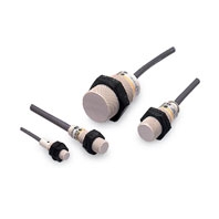 Proximity Sensor with Resin Case with Superb Water Resistance
|
Model |
E2F-X1R5E[] |
E2F-X2E[] |
E2F-X5E[] |
E2F-X10E[] |
|
|
Sensing distance |
1.5 mm ±10% |
2 mm ±10% |
5 mm ±10% |
10 mm ±10% |
|
|
Set distance |
0 to 1.2 mm |
0 to 1.6 mm |
0 to 4 mm |
0 to 8 mm |
|
|
Differential travel |
10% max. of sensing distance |
||||
|
Detectable object |
Ferrous metal (The sensing distance decreases with non-ferrous metal. Refer to Engineering Data on Data Sheet.) |
||||
|
Standard sensing object |
Iron, 8 × 8 × 1 mm |
Iron, 12 × 12 × 1 mm |
Iron, 18 × 18 × 1 mm |
Iron, 30 × 30 × 1 mm |
|
|
Response frequency *1 |
E/F Models: 2 kHz, |
E/F Models: 1.5 kHz, |
E/F Models: 600 Hz, |
E/F Models: 400 Hz, |
|
|
Power supply voltage |
E/FModels: 12 to 24 VDC (10 to 30 VDC), ripple (p-p): 10% max. |
||||
|
Current consumption |
E/FModels: 17 mA max. |
||||
|
Leakage current |
Y Models: 1.7 mA max. at 200 VAC (Refer to Engineering Data on Data Sheet.) |
||||
|
Control |
Load current |
E/FModels: 200 mA max. |
E/FModels: 200 mA max. |
||
|
Residual voltage |
E/FModels: 2 V max. (Load current: 200 mA, Cable length: 2 m) |
||||
|
Indicators |
E1 Models: Detection indicator (red), E2/F1/F2 Models: Operation indicator (red) |
||||
|
Operation mode |
E1/F1/Y1 Models: NO |
||||
|
Protection circuits |
E/F Models: Reverse polarity protection, Load short-circuit protection, Surge suppressor; Y Models: None |
||||
|
Ambient temperature range |
Operating/Storage: -25 to 70°C (with no icing or condensation) |
||||
|
Ambient humidity range |
Operating/Storage: 35% to 95% |
||||
|
Temperature influence |
±10% max. of sensing distance at 23°C in the temperature range of -25 to 70°C |
||||
|
Voltage influence |
E/F Models: ±2.5% max. of sensing distance at rated voltage in rated voltage ±15% range |
||||
|
Insulation resistance |
50 MΩ min. (at 500 VDC) between current-carrying parts and case |
||||
|
Dielectric strength |
E/F Models: 1,000 VAC, 50/60 Hz for 1 min between current-carrying parts and case |
||||
|
Vibration resistance |
Destruction: 10 to 55 Hz, 1.5-mm double amplitude for 2 hours each in X, Y, and Z directions |
||||
|
Shock resistance |
Destruction: 1,000 m/s2 10 times each in X, Y, and Z directions |
||||
|
Degree of protection |
IEC 60529 IP68, in-house standards: oil-resistant *2 |
||||
|
Connection method |
Pre-wired Models (Standard cable length: 2 m) |
||||
|
Weight (packed state) |
Approx. 40 g |
Approx. 50 g |
Approx. 130 g |
Approx. 170 g |
|
|
Materials |
Case |
Polyarylate resin |
|||
|
Sensing surface |
|||||
|
Clamping nuts |
Polyacetal |
||||
|
Accessories |
Instruction manual |
||||
1. The response frequency is an average value. Measurement conditions are as follows: standard sensing object, a distance of twice the standard sensing object, and a set distance of half the sensing distance.
2. When using the Sensor in environments subject to splashing cutting oil, deterioration may result due to the additives in the oil. The E2E is recommended in such environments.
OMRON Test Method
Usage conditions: 10 m or less under water in natural conditions
1. No water ingress after 1 hour under water at 2 atmospheres of pressure.
2. Sensing distance and insulation resistance specifications must be met after 20 repetitions of 1 hour in 0°C water and 1 hour in 70°C water.